V4+R VRF 50/60Hz
201702 39
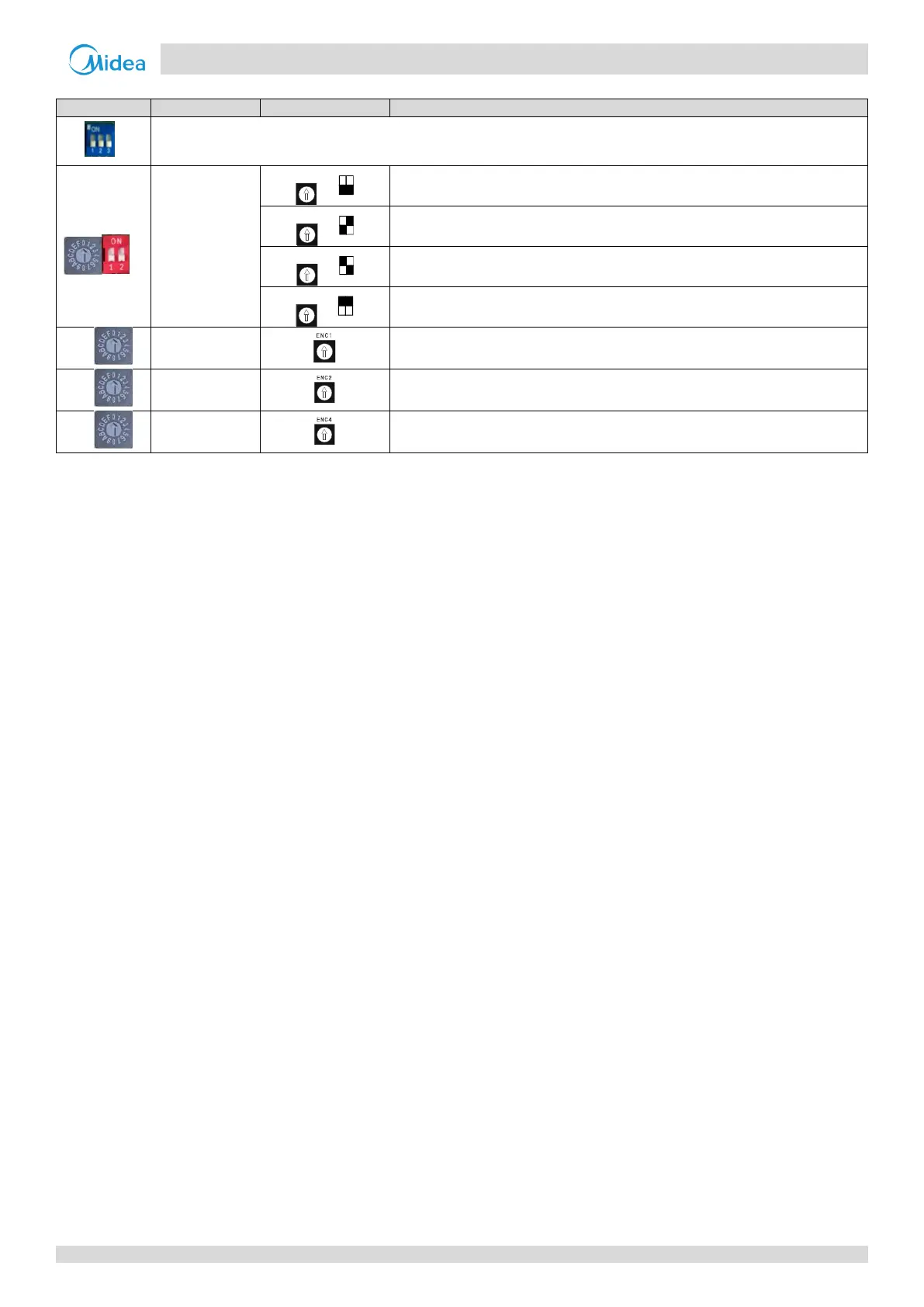
Table 4-1.1: Outdoor unit main PCB switch settings (continued)
The number of indoor units is in the range 0-15
0-9 on ENC3 indicate 0-9 indoor units; A-F on ENC3 indicate 10-15 indoor units
The number of indoor units is in the range 16-31
0-9 on ENC3 indicate 16-25 indoor units; A-F on ENC3 indicate 26-31 indoor units
The number of indoor units is in the range 32-47
0-9 on ENC3 indicate 32-41 indoor units; A-F on ENC3 indicate 42-47 indoor units
The number of indoor units is in the range 48-63
0-9 on ENC3 indicate 48-57 indoor units; A-F on ENC3 indicate 58-63 indoor units
Only 0, 1, 2, 3 should be selected
0 is for master unit; 1, 2, 3 are for slave units
Only 0, 1, 2, 3, 4, 5, 6, 7 should be selected
0: 8HP; 1: 10HP; 2: 12HP; 3: 14HP; 4: 16HP
Only 0, 1, 2, 3, 4, 5, 6, 7 should be selected
Notes:
1. Black denotes the switch position.
3. Switch ENC2 is factory-set and its setting should not be changed.