V4+R VRF 50/60Hz
94 201608
Midea V4+R Series Service Manual
… flowchart continued from previous page
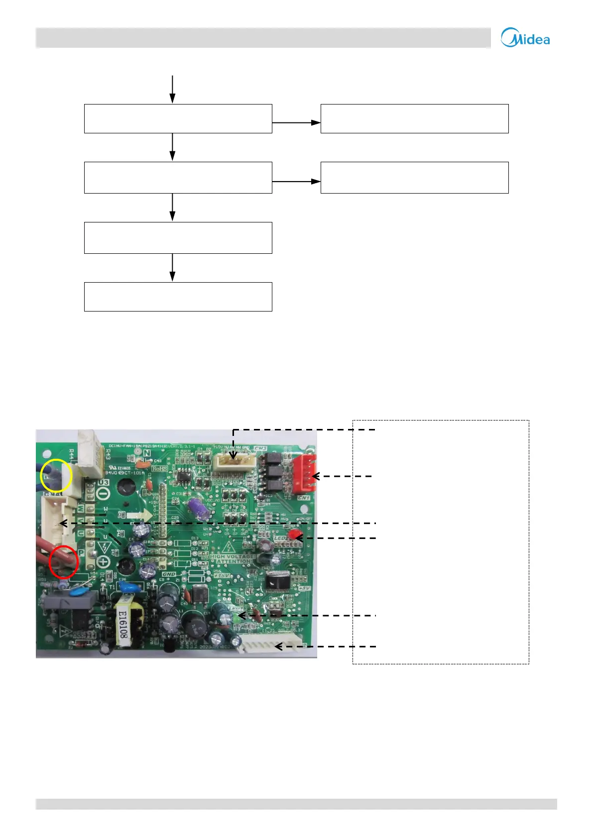
The power supply is abnormal
Check the power supply equipment
Voltage between P and N on fan module
is abnormal
4
Replacing the fan module resolves the
error
Notes:
1. Refer to Part 4, 1.1 “PCB Switches and Switch Settings”.
2. Refer to Figures 5-1.1 and 5-1.3 in Part 5, 1 “Outdoor Unit Electric Control Box Layout” and to the V5 X Engineering Data Book, Part 2, 5 “Wiring Diagrams”.
3. Refer to Part 2, 1 “Layout of Functional Components”.
4. The normal voltage between P and N on the fan module is 310V DC. Refer to Figures 5-1.1 and 5-1.3 in Part 5, 1 “Outdoor Unit Electric Control Box Layout”
and to Figure 5-4.18.
Figure 5-4.18: Fan module layout
Main PCB control signal input port
Power supply to fan motor
Fault LED indicator
Power supply LED indicator