www.roadwidener.com
24
Model SP-8 &10
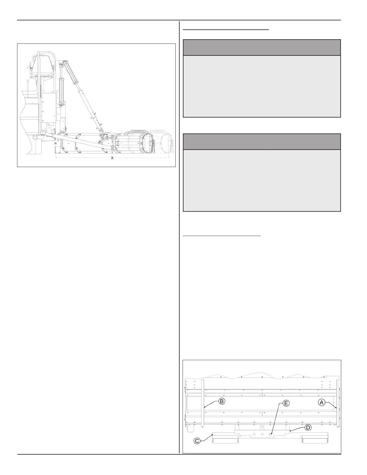
Following illustration shows different combinations of
blade sections with hydraulic extension.
Dimension X: 7 - 8.5 Ft Blade
• (1) - Pivot Section
• (2) - 1 Ft Section
• (1) - 2 Ft Section
• (1) - 2 - 3.5 Ft* Hydraulic Extension
* Projected stroke length at 45° Paving Angle.
Dimension X: 4 - 5.5 Ft Blade
• (1) - Pivot Section
• (1) - 1 Ft Section
• (1) - 2 - 3.5 Ft* Hydraulic Extension
* Projected stroke length at 45° Paving Angle.
10. Reinstall blade push tube anchor (G) at
approximately ½ to ⅔ of blade length. Reinstall
blade slope mount (F) at approximately ⅔ of blade
length. Use suitable hardware.
11. Reinstall slope tubes, push tubes and set up paving
and slope angles as in section 5.3.1.
12. Start engine, check operation and check for leaks.
Paving width can also be varied by adjusting the push
tubes and changing the blade paving angle. While
changing the blade paving angle material ow must be
taken into consideration. Depending on material ow, a
greater blade angle may be needed to ll entire spread
width. Narrow spread widths do not require as much
blade angle.
5.4 pusH roller setup
^ WARNING
Prevent serious injury or death.
Do not pull out push roller beyond 6th
hole.
Push roller assembly may fall out of tubes
and cause serious injury.
^ WARNING
Prevent serious injury or death.
Use caution while taking pivot pin out of
the push roller mount.
Push roller beam may fall out of push roller
mount and cause serious injury.
5.4.1 pIvot pIn loCAtIon
Pivot pin position for the push roller must be such that
push roller beam is symmetrically in middle between
end gates.
1. On a single sided machine, for right side paving,
location of left (A) and right (B) end gates are as
shown.
2. For this conguration, slide push roller beam (C)
towards left so pivot hole on push roller beam (C) is
in line with left hole on push roller mount (D).
3. Insert pivot pin (E) through in-line holes.