65
www.roadwidener.com
Model SP-8 & 10
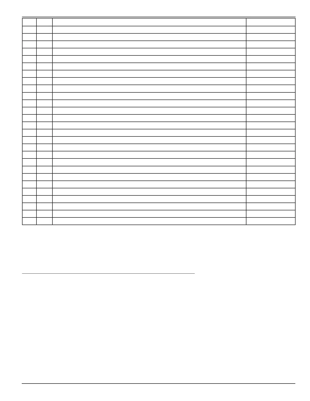
NO REQ DESCRIPTION PART NUMBER
1 REF HENDRICKSON AXLE, SP-066-25
2 REF BRAKE ACTUATOR MTG PLATE SP-143
3 REF GUSSET-BRAKE ACTUATOR MOUNT SP-168
4 2 BRAKE ACTUATOR, SAHR W/ # 7 SPRING, M18010
5 2 BRAKE ACTUATOR ROD WELDMENT SP-142
6 2 HEX NUT (METRIC) 10-1.5 HXN-M-10-1.5
7 2 HEX NUT, 5/8-18 UNF HXN-5/8-18
8 4 FLAT WASHER, 1/2 FLW-1/2
9 4 LOCK WASHER, 1/2 LKW-1/2
10 4 HEX NUT (METRIC) 12-1.75 HXN-M-12-1.75
11 REF BRAKE YOKE, 1/2 IN SST M18055
12 2 ADAPTER PLATE FOR HENDRICKSON SLACK ADJUSTERS SP-8 & 10 SP-1824
13 4 HEX HD CAP SCREW 5/16-18 UNC x 1-1/4 HCS-5/16-18-1.25
14 4 HEX NUT, 5/16-18 UNC HXN-5/16-18
15 4 LOCK WASHER, 5/16 LKW-5/16
9.4.1 InstruCtIons for BrAke yoke InstAllAtIon And Adjustment:
1. Block the SP wheels, start the engine and apply hydraulic pressure to the SAHR (Spring Applied Hydraulic
Release) canister to release the brakes.
2. Install the brake yoke as shown with adjuster hex (B) inboard.
3. Manually rotate the adjuster arm (C) to align with the slot as shown in view B.
4. Adjust item (5) linkage to connect to item (11) brake yoke.
5. Insert the at end of the stud (D) through the bushing of the adjuster arm. The shoulder adjacent to the
threaded end of the stud must engage the slot properly to prevent the stud from rotating. Install the 7/16 ange
head nut. Tighten to 40-50 ft-lb.
6. After installation, adjuster must be manually adjusted by rotating adjuster hex (B) clockwise until the brake
lining contacts the drum.
7. Rotate adjuster hex counter-clockwise 1/2 turn. A minimum of 13 ft-lb is necessary to overcome the clutch.
Ratcheting sound will occur.
8. The brakes are now disengaged and the adjusters are set.