47
www.roadwidener.com
Model SP-8 & 10
NOTICE
Prevent machine damage.
Failure to perform ushing procedure after
a pump, motor or hose failure will result
in a repeat failure and will void machine
warranty.
Either the conveyor loop or traction drive loop can be
ushed, depending on which loop has failed. If there is
a concern that both loops have debris, refer to Flushing
Conveyor And Traction Drive Systems in section 6.4.3.
6.4.1 flusH Conveyor system
1. Drain and remove hydraulic tank.
2. Clean or replace both suction strainers and ush
out tank.
3. Install tank and replacement components.
NOTICE
Prevent machine damage.
Do not pour hydraulic oil directly into
closed loop circuit hoses or a failure will
occur.
In following detail, major steps are mentioned as “Step
#“ for dual side machine or as “Step #A“ for single
sided machine where applicable. These steps refer to
the schematic description with same headings.
step 1 or 1A
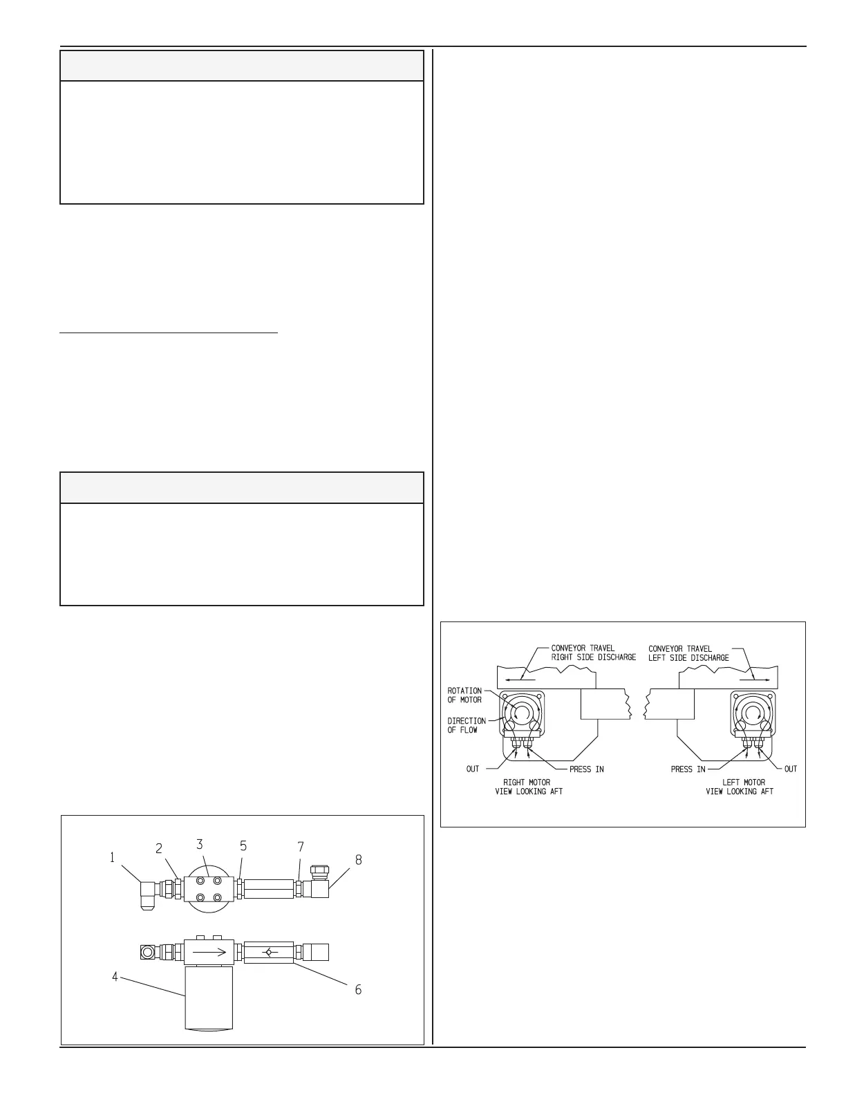
1. Assemble lter kit using dealer or customer supplied
components as shown below.
1 - 90° Elbow, 3/4 FNPT x FJIC Swivel
2 - Adapter, 1 MNPT x 3/4 MJIC
3 - Filter Head Donaldson #P166664
4 - Filter, Donaldson #P163555
5 - Adapter, 1 MNPT x 3/4 MNPT
6 - Check Valve, Danfoss #3C14-6-65
7 - Adapter, 3/4 MNPT x 3/4 MNPT
8 - 90° Elbow, 3/4 FNPT x FJIC Swivel
2. Install lter kit as shown in step 1 or step 1A
in schematics . Connect item #8 directly to pump
tting. Check valve prevents inadvertent back ow
or back ush into the loop.
3. If ow and pressure values are required for a new
pump installation, set up ow meter, valve and
gauge in loop prior to ushing. This will insure that
ow meter and gauges do not introduce debris after
ushing.
step 2 or 2A
1. On operator’s console, toggle conveyor direction
switch for right side discharge and turn off ow
control. Right and left side is dened as relative to
operator in seat.
2. Follow pressure hose back from right side motor
to pump. This should be port “C” on pump. Verify
motor rotation and hoses as follows:
3. Label and disconnect two hoses at each motor and
connect to each other using a 3/4 MJIC x 3/4 MJIC
adapter. This is shown as step 2 (for dual side) and
2A (for single sided).
4. Start the engine and slowly increase conveyor ow
until lter’s “visual service indicator” is positioned
in center of the window. If pump goes over relief,
the ow is going against check valve. Stop the
ow, then reverse conveyor direction or hoses.