English-42
004-1055-00
TP210 Rev. A
© 2013 Midmark Corp. | 60 Vista Drive Versailles, OH 45380 USA | 1-800-643-6275 | 1-937-526-3662 |
[Revised: 6/5/14]
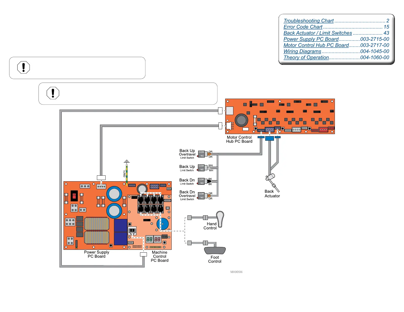
Back Function / Fuses and Connections
Isolating a Malfunction
This illustration shows only the fuses and connections that affect the Back UP / DOWN function.
J4
J1
J2
F1
F2
F3
F4
J9
J10
J13
J2 J3 J4 J5
J8
J9 J10 J11
J6
J12
S2
J19
J3
J5
J7
J6
J18
J1
115V
J16
J4
J1
J2
F1
F2
F3
F4
F5
J9
J10
J11
J2 J3 J4 J5
J8
J9 J10 J11
J6
J12
S2
J19
J3
J5
J7
J6
J18
J1
115V
J16
J14
J13
J12
J11
J10
J8
J7
J6
J4
J3
J2
F3
J9 J5 J1
TPD1
TPD2
TPD3
TPC1
TPC2
TPC3
TPB1
TPB2
TPB3
TPA
J15
Equipment Alert
Anytime the limit switch wires or the actuator wires
are disconnected, the PC Board must be calibrated.
Troubleshooting Chart .................................... 2
Error Code Chart .......................................... 15
Back Actuator / Limit Switches ..................... 43
Power Supply PC Board ...............003-2715-00
Motor Control Hub PC Board........003-2717-00
Wiring Diagrams ...........................004-1045-00
Theory of Operation......................004-1060-00
Equipment Alert
Always remove power from table before disconnecting or connecting
J13 on Motor Control Hub PC Board or damage to PC Board may occur.