English-44
004-1055-00
TP210 Rev. A
© 2013 Midmark Corp. | 60 Vista Drive Versailles, OH 45380 USA | 1-800-643-6275 | 1-937-526-3662 |
[Revised: mm/dd/yr]
J14
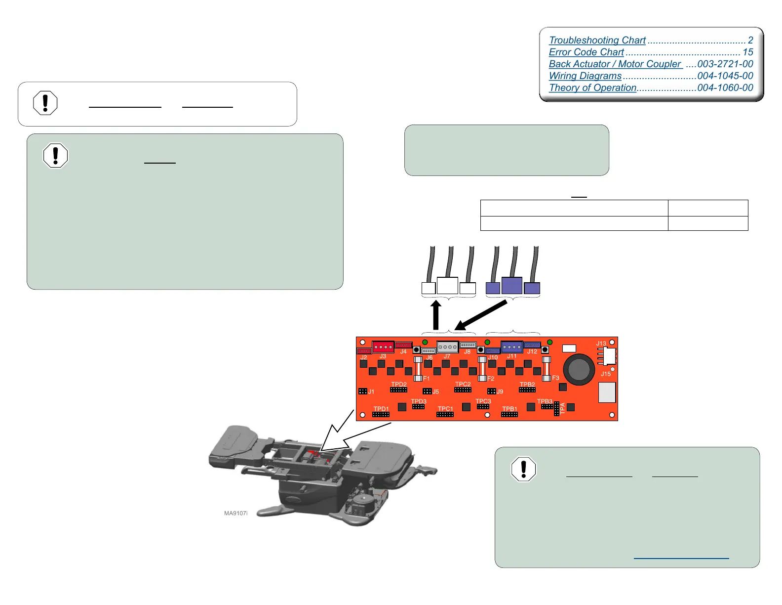
Back Actuator Test
Isolating a Malfunction
Equipment Alert
Failure to move all three connections
may result in damage to table.
Step 1:
A) Disconnect power to the table.
B) Disconnect Tilt actuator connections.
C) Move Back wire connection J10 to Tilt PC Board connection J6.
D) Move Back wire connection J11 to Tilt PC Board connection J7.
E) Move Back wire connection J12 to Tilt PC Board connection J8.
F) Connect power to table.
Equipment Alert
The wire connections and wire routing must be put
back in original locations before installing covers.
Step 2: Using the hand / foot control:
A) Press & hold Tilt UP button briefly.
B) Press & hold Tilt DOWN button briefly.
Equipment Alert
The wire connections and wire routing must be put
back in original locations before installing covers.
Step 3:
A) Reconnect Back actuator connections.
B) Reconnect Tilt actuator connections.
C) Calibrate Table. Refer to: Calibration Procedure
Motor Control Hub PC Board
Troubleshooting Chart .................................... 2
Error Code Chart .......................................... 15
Back Actuator / Motor Coupler ....003-2721-00
Wiring Diagrams ...........................004-1045-00
Theory of Operation......................004-1060-00
Troubleshooting Chart .................................... 2
Error Code Chart .......................................... 15
Back Actuator / Motor Coupler ....003-2721-00
Wiring Diagrams ...........................004-1045-00
Theory of Operation......................004-1060-00
Did Back move Up and Down in Step 2? Required Action
YES Actuator is OK
NO Replace actuator