EXP-925
Midtronics B.V. Hoofdveste 6 - 8 Houten NL
www.midtronics.com
21
Chapter 6: Cable Drop Test
If the test results for the starter or charging systems indicate
that there may be a problem, you may want to perform the
Cable Drop Test to determine if it is due to worn cables or
bad connections between the battery and the alternator
or starter. Worn cables or bad connections create higher
resistance, which causes a drop across the circuit. The
voltage drop reduces current carrying capability that
displays the same symptoms as a weak alternator or starter
and causes premature battery failure.
There’s no need to run the engine. The Cable Drop Test
uses Midtronics’ conductance technology to send a signal
through the circuit at the component under test. The tester
then simultaneously calculates voltage drop on the positive
(+) and negative (–) sides of any circuit as well as the total
voltage drop. The amperage range for each of the four tests
is 0 to 1000 A. When you change the setting from the factory
defaults, the tester will store your setting in memory for your
next test.
There are three preset tests:
• BATTERY GROUND
• STARTER CIRCUIT
• ALTERNATOR CIRCUIT
A fourth test, OTHER CIRCUIT, tests other grounds and
circuits against your specied amperage capacity.
The test requires two test lead connections:
• Battery test leads at the component’s output lead (the
B+ or output screw on the alternator) and the compo-
nent’s housing as ground
• DMM test leads at the battery terminals
NOTE: The test requires a complete circuit. If you’re
testing a system with a remote solenoid, you can test
from the battery to the solenoid, but not from the
battery to the starter.
R
Battery
Battery Test Lead
DMM Test Lead
Component
Under
Test
1
R
2
+
–
Red Red
Black Black
Connections for the Cable Drop Test
To begin, select the Cable Drop Test icon in the Main Menu
and follow the instructions on the display.
IMPORTANT: For accurate results the battery should be
good and fully charged before you perform a test.
Battery Ground Test
The Battery Ground Test measures the voltage drop for the
ground strap.
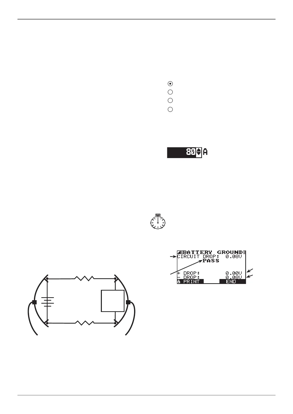
1. SELECT CIRCUIT: Use the UP/DOWN ARROWS or the
numerical keypad to select the Battery Ground Test.
1 BATTERY GROUND
2 STARTER CIRCUIT
3 ALTERNATOR CIRCUIT
4 OTHER CIRCUIT
Press the NEXT soft key to continue.
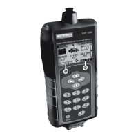
2. SET AMPS: Use the UP/DOWN ARROWS or the
keypad to select the rated amperage of the circuit you
are testing. The default is 80 A.
Press the NEXT soft key to continue.
3. Connect the positive (+) clamp of the battery test leads
to the starter’s battery terminal stud. Connect the nega-
tive (–) clamp to the starter’s housing.
4. Connect the positive (+) DMM clamp to the battery’s
positive (+) post. Connect the negative clamp (–) to the
battery’s (–) negative post.
For the next few seconds the Tester will display the
word TESTING and a stopwatch while it evaluates
the battery ground.
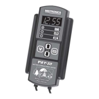
Battery Ground Test Results
Battery Ground Test PASS Result
If there is a problem, the decision is CLEAN AND RETEST OR
REPLACE. To print the results, align the Tester’s IR transmitter
with the printer’s receiver, and select the PRINT soft key.
To return to the Main Menu, press the END key.
Chapter 6: Cable Drop Test
(EST version only)
Voltage drop
across nega-
tive side of
circuit
Total
circuit
voltage
drop
Voltage drop
across posi-
tive side of
circuit
Decision