EXP-925
Midtronics B.V. Hoofdveste 6 - 8 Houten NL
www.midtronics.com
22
Chapter 6: Cable Drop Test
Starter Circuit
The Starter Circuit Test measures the voltage drop of the
starter circuit.
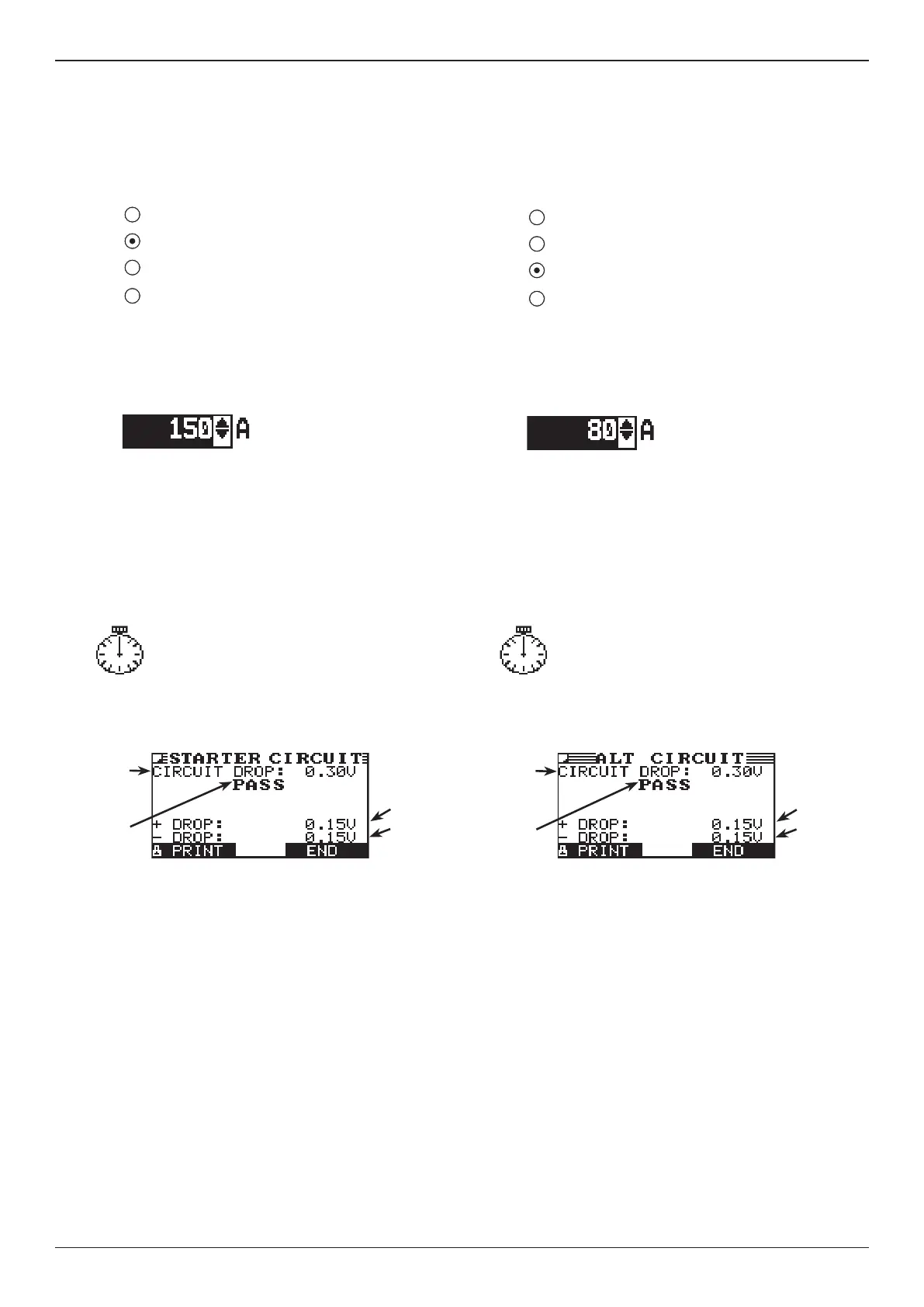
1. SELECT CIRCUIT: Use the UP/DOWN ARROWS or the
numerical keypad to select the Battery Ground Test.
1 BATTERY GROUND
2 STARTER CIRCUIT
3 ALTERNATOR CIRCUIT
4 OTHER CIRCUIT
Press the NEXT soft key to continue.
2. SET AMPS: Use the UP/DOWN ARROWS or the
keypad to select the rated amperage of the starter
circuit. The default is 150 A.
Press the NEXT soft key to continue.
3. Connect the positive (+) clamp of the battery test leads
to the starter’s battery terminal stud. Connect the nega-
tive (–) clamp to the starter’s housing.
4. Connect the positive (+) DMM clamp to the battery’s
positive (+) post. Connect the negative clamp (–) to the
battery’s (–) negative post.
For the next few seconds the Tester will display
the word TESTING and a stopwatch while it
evaluates the battery ground.
Starter Circuit Test Results
Starter Circuit PASS Result
If there is a problem, the decision is CLEAN AND RETEST OR
REPLACE. To print the results, align the Tester’s IR transmitter
with the printer’s receiver, and select the PRINT soft key.
To return to the Main Menu, press the END key.
Alternator Circuit
The Alternator Circuit Test measures the voltage drop of the
alternator circuit.
1. SELECT CIRCUIT: Use the UP/DOWN ARROWS or the
numerical keypad to select the Battery Ground Test.
1 BATTERY GROUND
2 STARTER CIRCUIT
3 ALTERNATOR CIRCUIT
4 OTHER CIRCUIT
Press the NEXT soft key to continue.
2. SET AMPS: Use the UP/DOWN ARROWS or the
keypad to select the rated amperage of the alternator
circuit. The default is 80 A.
Press the NEXT soft key to continue.
3. Connect the positive (+) clamp of the battery test leads
to the starter’s battery terminal stud. Connect the nega-
tive (–) clamp to the starter’s housing.
4. Connect the positive (+) DMM clamp to the battery’s
positive (+) post. Connect the negative clamp (–) to the
battery’s (–) negative post.
For the next few seconds the Tester will display
the word TESTING and a stopwatch while it
evaluates the battery ground.
Alternator Circuit Test Results
Alternator Circuit PASS Result
If there is a problem, the decision is CLEAN AND RETEST OR
REPLACE. To print the results, align the Tester’s IR transmitter
with the printer’s receiver, and select the PRINT soft key.
To return to the Main Menu, press the END key.
Voltage drop
across nega-
tive side of
circuit
Total
circuit
voltage
drop
Voltage drop
across posi-
tive side of
circuit
Decision
Voltage drop
across nega-
tive side of
circuit
Total
circuit
voltage
drop
Voltage drop
across posi-
tive side of
circuit
Decision