OM-273476 Page 18
SECTION 5 – INSTALLATION
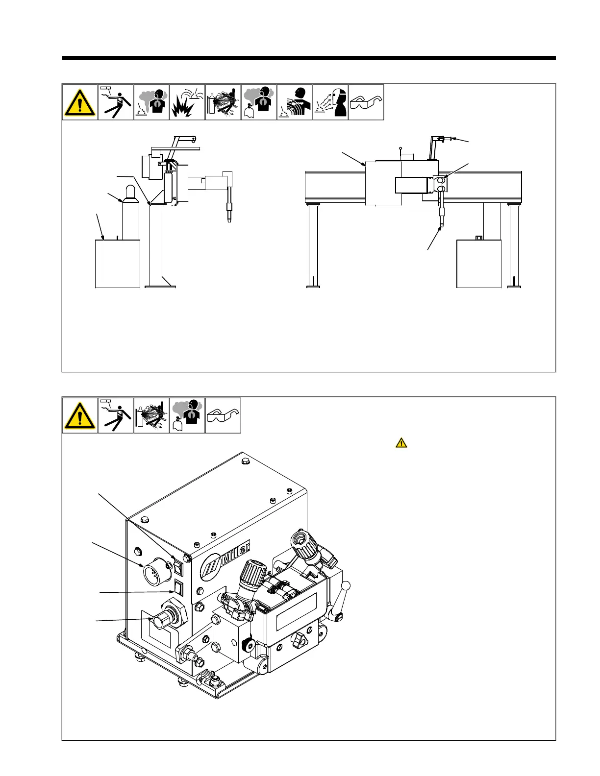
5-1. Typical Equipment Location
1 Welding Power Source
2 Gas Cylinder
3 Side Beam
4 Weld Control
5 Spool Support
6 Wire Drive Assembly
7 Automatic Welding Gun
5-2. Shielding Gas And Cooler Connections (CE Model)
Turn off power before making
connections.
1 Jog/Retract Switch
2 10 Socket Control Receptacle RC3
3 Gas Purge Switch
Connect control cable from rear of welding
power source to wire drive assembly.
To make connections, align keyway, insert
plug, and tighten threaded collar.
4 Shielding Gas Valve Fitting
Requires hose fitting with 5/8–18 right-hand
threads.
For guns requiring external gas connections,
remove hose from barbed fitting near gun/
feeder opening and connect to gun.
F
Shielding gas pressure noy to exceed
100 psi (689 kPa).
 Loading...