OM-243 347 Page 34
SECTION 9 − MAINTENANCE & TROUBLESHOOTING
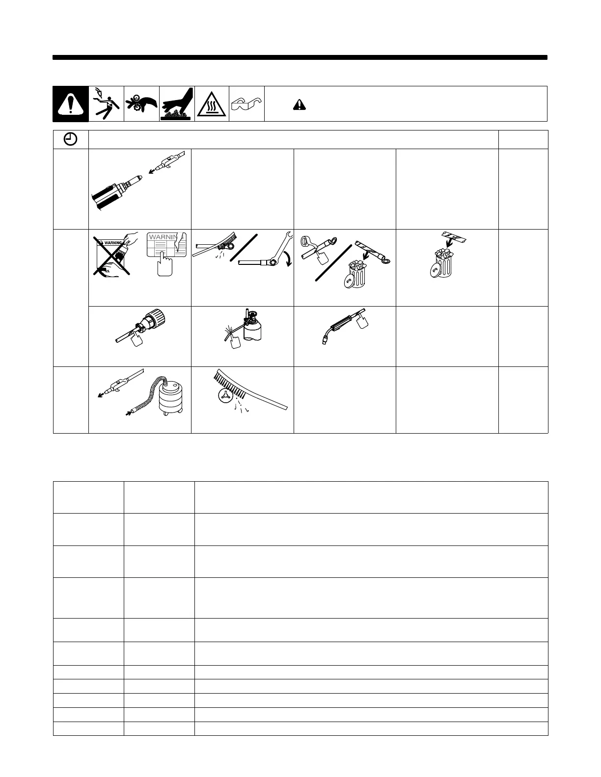
9-1. Routine Maintenance
! Disconnect power before maintaining.
n = Check ~ = Clean l = Replace
Every
Spool
of Wire
or Wire
Change
n~ Gun Liner
Every
3
Months
l Unreadable Labels ~ Weld Terminals nl Weld Cable l Cracked Parts
n 14-Pin Cord n Gas Hose and Fittings n Gun Cable
Every
6
Months
Or
~ Inside Unit ~ Drive Rolls
9-2. Diagnostics
The following error messages are shown on the displays to indicate specific errors. Explanations are in the text below:
TRIG ERR Indicates a trigger error. A trigger error occurs if the user has the trigger held for more than two
minutes without striking an arc. This error also occurs if the trigger is held when the feeder is powered
up. The error may be cleared by releasing the trigger.
JOG ERR Indicates a jog switch error. A jog switch error occurs if the user has the jog switch held for more than
two minutes. This error also occurs if the jog switch is held when the feeder is powered up. The error
may be cleared by releasing the jog switch.
PURG ERR Indicates a purge switch error. A purge switch error occurs if the user has the purge switch held for
more than one minute. This error also occurs if the purge switch is held when the feeder is powered
up. The error may be cleared by releasing the purge switch.
COOL ERR Indicates a water flow switch error. A water flow switch error occurs if no water flow is detected while
the trigger is pressed. Jog and purge switches will behave normally even if no water flow is detected.
Dip switch 2 on the motor control pcb must be set to enable this error. The error is cleared when wa-
ter flow is detected or when the error is disabled.
TEST ERR.1 or
ERR.2
Indicates a power on self diagnostic test error. The number provides information regarding the error.
If this error occurs, contact a Factory Authorized Service Agent.
COMM ERR Indicates a serial communication error. A communication error occurs 2 seconds after a loss of com-
munication between the motor control pcb and the front panel pcb.
1234 ERR.M Indicates a motor control pcb error. If this error occurs, contact a Factory Authorized Service Agent.
1234 ERR.F Indicates a front panel pcb error. If this error occurs, contact a Factory Authorized Service Agent.
R.Tac ERR Indicates the right push motor tachometer circuit has an error.
L.Tac ERR Indicates the left push motor tachometer circuit has an error.
G.Tac ERR Indicates tachometer in push-pull gun has an error.