EasyManua.ls Logo

Miller D-74 MPa Plus User Manual

Miller D-74 MPa Plus
52 pages
To Next Page IconTo Next Page
Page #1 background imageLoading...
Page #1 background image
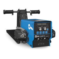
D-74 MPa Plus
Processes
Description
MIG (GMAW) Welding
MIG (GMAW-P) Welding
Flux Cored (FCAW) Welding
(Gas- And Self-Shielded)
Wire Feeder
Aluminum Push/Pull Capable
OM-243 347G
201407
File: MIG (GMAW)
Visit our website at
www.MillerWelds.com
CE

Table of Contents

Questions and Answers:

Miller D-74 MPa Plus Specifications

General IconGeneral
BrandMiller
ModelD-74 MPa Plus
CategoryWelding System
LanguageEnglish

Summary

From Miller to You

Section 1: Safety Precautions

Symbol Usage and Arc Welding Hazards

Explains hazard symbols and potential dangers associated with arc welding processes.

Additional Safety Symbols and Maintenance Precautions

Details additional safety symbols for installation, operation, maintenance, and general hazards.

Proposition 65, Safety Standards, and EMF Information

Covers California warnings, principal safety standards, and electromagnetic field (EMF) information.

Section 2: French Safety Precautions

French Safety Symbols and Arc Welding Hazards

Details safety symbols and potential dangers related to arc welding in French.

Installation, Operation, and Maintenance Safety

Covers additional safety concerns for installation, operation, and maintenance.

Proposition 65, Safety Standards, and EMC Information (French)

Provides California warnings, safety standards, and EMC information in French.

Section 3: Definitions

Additional Safety Symbols and Definitions

Explains specific safety symbols found on CE products and their meanings.

Miscellaneous Symbols and Definitions

Defines various symbols used in the manual, including electrical and operational terms.

Section 4: Specifications

Serial Number, Unit, and Environmental Specifications

Details serial number location, unit specifications, and environmental operating conditions.

Section 5: Installation

Site Selection and Equipment Connection Diagrams

Guidance on selecting a suitable installation site and diagrams for equipment connections.

Rear Panel Connections and Drive Assembly

Details rear panel connections and instructions for the rotating drive assembly.

14-Pin Plug Info and Wire Feed Speed Table

Information on 14-pin plug connections and a table for wire type, size, and feed speed.

Installing Welding Gun

Step-by-step instructions for installing the welding gun, including push/pull options.

Installing and Threading Welding Wire

Procedure for installing and threading the welding wire into the feeder for optimal feeding.

Section 6: Operation

Power Switch and Jog/Purge Switch

Describes the main power switch and the jog/purge switch functions for wire feeding.

Front Panel Controls Overview

Details all controls on the front panel, including displays, adjust controls, and push buttons.

Left and Right Display Functions

Explains the information displayed on the left and right displays, including voltage, arc length, and wire feed speed.

Parameter Adjustment and Setup Buttons

Covers adjusting parameters with controls and using setup, start, and crater push buttons.

Display Navigation and Power Source Selection

How to navigate displays and select the appropriate power source for the wire feeder.

Operational Terms

Defines key terms and sequences used in the wire feeder's operation and programming.

Section 7: Setting Sequence Parameters

Sequence Parameters in a Program

Details the parameters for weld sequences like preflow, start, weld, crater, and postflow.

Section 8: Programming

Setup Menu

Explains how to enter and navigate the main setup menu for configuring the wire feeder.

Setup Menu Level 2 and Parameter Locking

Covers advanced setup options, parameter locking, and range limits.

Setting Start Sequence (Synergic Pulse)

Guides on setting up the start sequence parameters for synergic pulse welding.

Setting Start Sequence (Non-Synergic Pulse/MIG)

Guides on setting up start sequence parameters for non-synergic pulse or MIG welding.

Setting Crater Fill Sequence (Synergic Pulse)

Instructions for setting crater fill parameters in synergic pulse welding for a smooth weld end.

Setting Crater Fill Sequence (Non-Synergic Pulse/MIG)

Instructions for setting crater fill parameters in non-synergic pulse or MIG welding.

Profile Pulse Feature

Details the Profile Pulse feature for optimizing aluminum weld bead appearance.

Section 9: Maintenance & Troubleshooting

Routine Maintenance and Diagnostics

Covers regular maintenance checks and diagnostic error codes for troubleshooting.

Troubleshooting Common Issues

Provides solutions for common operating problems and error messages.

Section 10: Electrical Diagram

Section 11: Parts List

Main Assembly Parts

Diagram and list of parts for the main assembly of the wire feeder.

Control Box Parts

Diagram and list of parts for the control box assembly.

Drive Assembly and Wire Components

Diagram and list of parts for the drive assembly and associated wire components.

Drive Roll and Wire Guide Kits

Table listing drive roll and wire guide kits compatible with different wire sizes.

Warranty Information

Owner's Record

Service and Support Information

Related product manuals