OM-243 347 Page 15
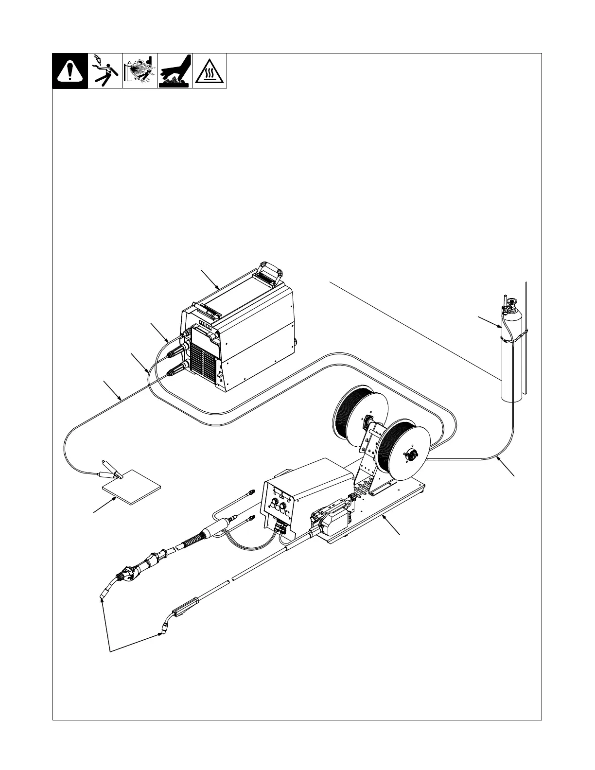
5-2. Equipment Connection Diagrams
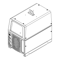
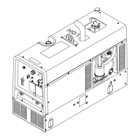
1 Welding Power Source
. Select welding power source
according to Section 6-11.
2 Contactor Control/Power Cord
3 Positive (+) Weld Cable
4 Negative (−) Weld Cable
5 Workpiece
6 Welding Gun
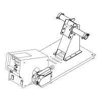
7 Wire Feeder
8 Gas Hose
9 Gas Cylinder and Regulator
(Customer Supplied)
. Shielding gas pressure not to
exceed 100 psi (689 kPa).
245 240-A
1
2
3
4
5
6
7
8
9