OM-293 Page 14
SECTION 3 − OPERATION
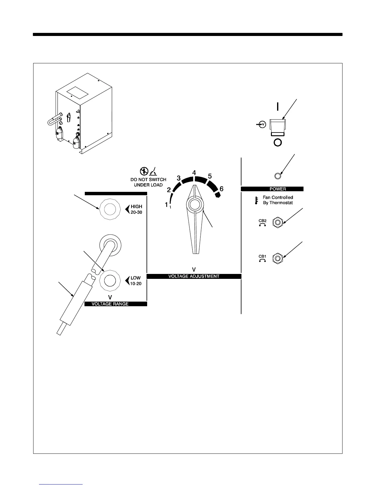
3-1. Controls
1 Voltage Range Selector Plug
Use plug position to select voltage range.
2 High Range Receptacle
3 Low Range Receptacle
To connect to a receptacle, insert plug.
4 Voltage Adjustment Switch
Use switch to adjust voltage within range se-
lected by Voltage Range Selector plug. Each
position of the switch is a change of 2 volts.
Y Do not change position of Voltage
Range selector plug or Voltage Ad-
justment switch while welding. Ar-
cing can damage contacts, causing
connections to fail.
5 Power Switch
6 Pilot Light
7 Circuit Breaker CB2
If CB2 opens, the 24 volts ac output to the Re-
mote 14 receptacle stops.
8 Circuit Breaker CB1
If CB1 opens, the 115 volts ac output to the
Remote 14 receptacle stops.
Press button to reset circuit breakers.
2
5
4
Ref. ST-121 471-F / Ref. ST-186 125
3
6
8
7
1