OM-236297 Page 7
SECTION 5 − INSTALLATION
. Be sure that contact tip, liner, and drive rolls are correct for wire size and type. See Parts List to change parts as needed.
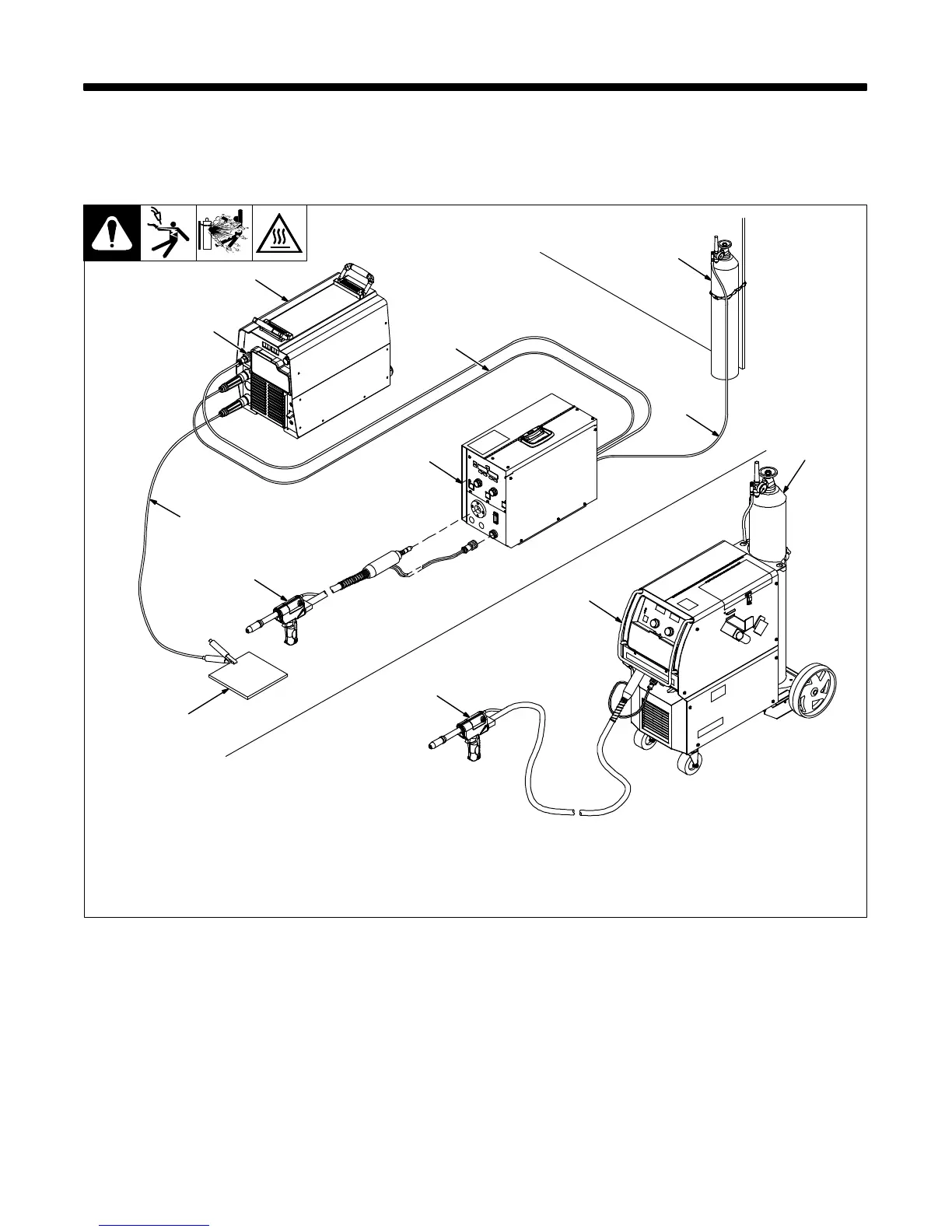
5-1. Connections With A Constant Current (CC), Constant Voltage (CV) Or Constant
Current/Constant Voltage (CC/CV) Welding Power Source Having A 14-Socket
Receptacle
Ref. 151 666-G / 250 586-A / 804 653-A / 245 997-A
3
4
6
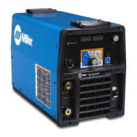
Millermatic 350P
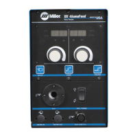
XR D Control
9
1 CV Or CC/CV Welding Power Source
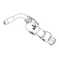
2 24 VAC/Contactor Control 14-Pin
Plug
3 Negative (−) Weld Cable
4 Workpiece
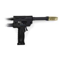
5 Welding Gun
6 Wire Feeder
7 Positive (+) Weld Cable
8 Gas Hose
9 Gas Cylinder
. Shielding gas pressure not to exceed
100 psi (689 kPa).
7
8
9
2
1
5
5
1
 Loading...