SECTION III
INSTALLATION
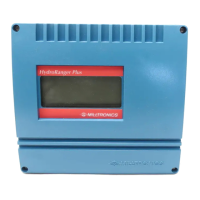
HydroRanger I
The HydroRanger I should be mounted in an area that is within the unit’s ambient
temperature range and is suitable for the specified enclosure. The front cover should be
accessible for calibrating and viewing.
It is advisable to keep the HydroRanger I away from high voltage or current runs,
contactors and SCR control drives.
DO NOT MOUNT THE HydroRanger I
IN DIRECT SUNLIGHT
WITHOUT THE USE OF A SUN SHIELD
Refer to Figure 1 for outline and mounting dimensions.
Transducer
NOTE: Wiring of transducer cable must be done in conjunction with approved
conduit, boxes and fittings and to procedures in accordance with all
governing regulations. All transducer cabling must be run in grounded
metal conduit for optimum noise rejection. Refer to Figure 4 for outline
and wiring.
1. Mount the transducer above the highest anticipated material level by at least
30 cm (1 ft).
2. Install the transducer so that it can have a clear sound path perpendicular to
the liquid surface.
3. To avoid false echoes, install the transducer such that the sound path will
not intersect vessel fill spouts, rough vessel walls, ladders ... etc. Where
possible, the transducer should be mounted 0.3 m (1 ft) from the closest
vessel wall for every 3 m (10 ft) of depth.
Example: if the vessel is 10 m deep, the transducer should be mounted
at least 0.3 m/3 m x 10 m = 1.0 m from the closest vessel wall.
Programmer
In order to calibrate the HydroRanger I, a programmer must be set into the recess on
the HydroRanger I front cover. It can be removed when operating in the RUN mode.
(Note: since a programmer need not be ordered with each unit, check your order if you
think that the programmer is missing).
PL-399 3 – 1