Table of Contents
I GENERAL INFORMATION
Important 1 – 1
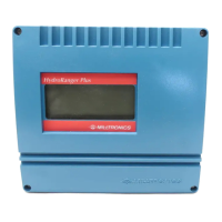
HydroRanger I 1 – 1
II SPECIFICATIONS
HydroRanger I 2 – 1
Programmer 2 – 2
Transducer 2 – 2
Alternate Temperature Sensor 2 – 3
Current Output Isolator 2 – 3
Cabling 2 – 3
III INSTALLATION
HydroRanger I 3 – 1
Transducer 3 – 1
Programmer 3 – 1
Current Output Isolator 3 – 2
Interconnection 3 – 2
Synchronization 3 – 2
Internal Checks 3 – 3
IV START-UP
General 4 – 1
Programmer Keypad Summary 4 – 2
Parameter Entry 4 – 3
Display Messages 4 – 6
V FUNCTIONAL
Transceiver 5 – 1
Transducer 5 – 1
Damping and Process Rate 5 – 1
Temperature Compensation 5 – 2
Sound Velocity 5 – 3
Blanking 5 – 3
Agitator Discrimination 5 – 4
Relays 5 – 5
Analog Output 5 – 10
VI APPLICATIONS
Simple Level Application 6 – 3
Example 1
Pump Control Application 6 – 7
Example 2
i