© 2009 MIMAKI ENGINEERING CO.,LTD.
6.2.8 P.1
1
2
3
4
5
6
7
8
R.1.0
Maintenance Manual > Disassembly and Reassembly > Ink-related Parts > Valve Assy
Model CJV30/TPC Issued 2008.08.04 Revised F/W ver. 1.00 Remark
1.0
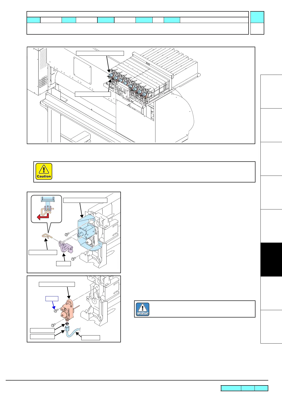
6.2.8 Valve Assy
Work procedures
1. Execute [MACHINE SETUP] — [#ADJUST] — [HEAD
ADJUST] — [HEAD WASH] to discharge the ink.(See 4.2.7)
2. Remove the following covers.
• ICU Cover F
• ICU Cover R
3. Remove snap pin A and then the link.
4. Removes screws to take off the cartridge solenoid BKT A
together with the solenoid.
5. Remove the valve N-3 M6 assy and loosen the joint screws to
remove the tube.
6. Reverse the disassembly procedure for reassembly.
Use protection glasses and gloves during works.
Depending on the working condition, ink may reach your eyes or your skin may be roughed due to ink.
Ink Cartridge Solenoid Assy
Valve N-3 M6 Assy
Link
Snap pin A
Cartridge Solenoid BKT A
Screw
Valve N-3 M6 Assy
O-ring
Joint Screw
Tube
Take care not to contaminate the surroundings with ink.
Also, take care not to lose the O-ring.

 Loading...


