© 2009 MIMAKI ENGINEERING CO.,LTD.
6.3.3 P.1
1
2
3
4
5
6
7
8
R.1.1
Maintenance Manual > Disassembly and Reassembly > Cut Head Carriage > Mark Assy
Model CJV30/TPC Issued 2008.08.04 Revised 2008.09.17 F/W ver. 1.20 Remark
1.1
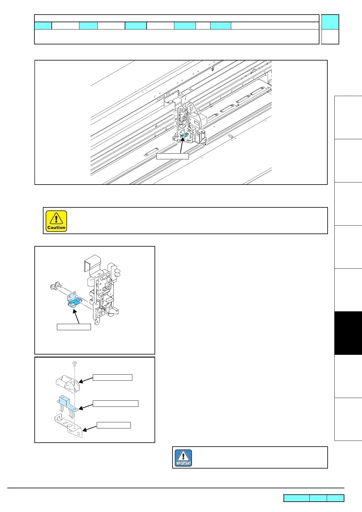
6.3.3 Mark Assy
Work procedures
1. Remove the pen assy.
• Refer to “6.3.1 Pen Assy and LED Pointer”.
2. Remove the connector (CN3) of the mark sensor assy from the
cutter slider PCB assy.
3. Remove the mark sensor assy together with the T sensor BKT
from the rear of the printer.
4. Remove the T sensor cover and then mark sensor assy.
5. Reverse the disassembly procedure for reassembly.
Be sure to turn off the main circuit breaker to prevent unexpected movements of the printer.
T Sensor BKT
Mark Sensor Assy
T Sensor Cover
In reassembly, pay attention to harness treatment.

 Loading...


