7-12 BeneVision N17/BeneVision N15/BeneVision N12 Patient Monitor Service Manual
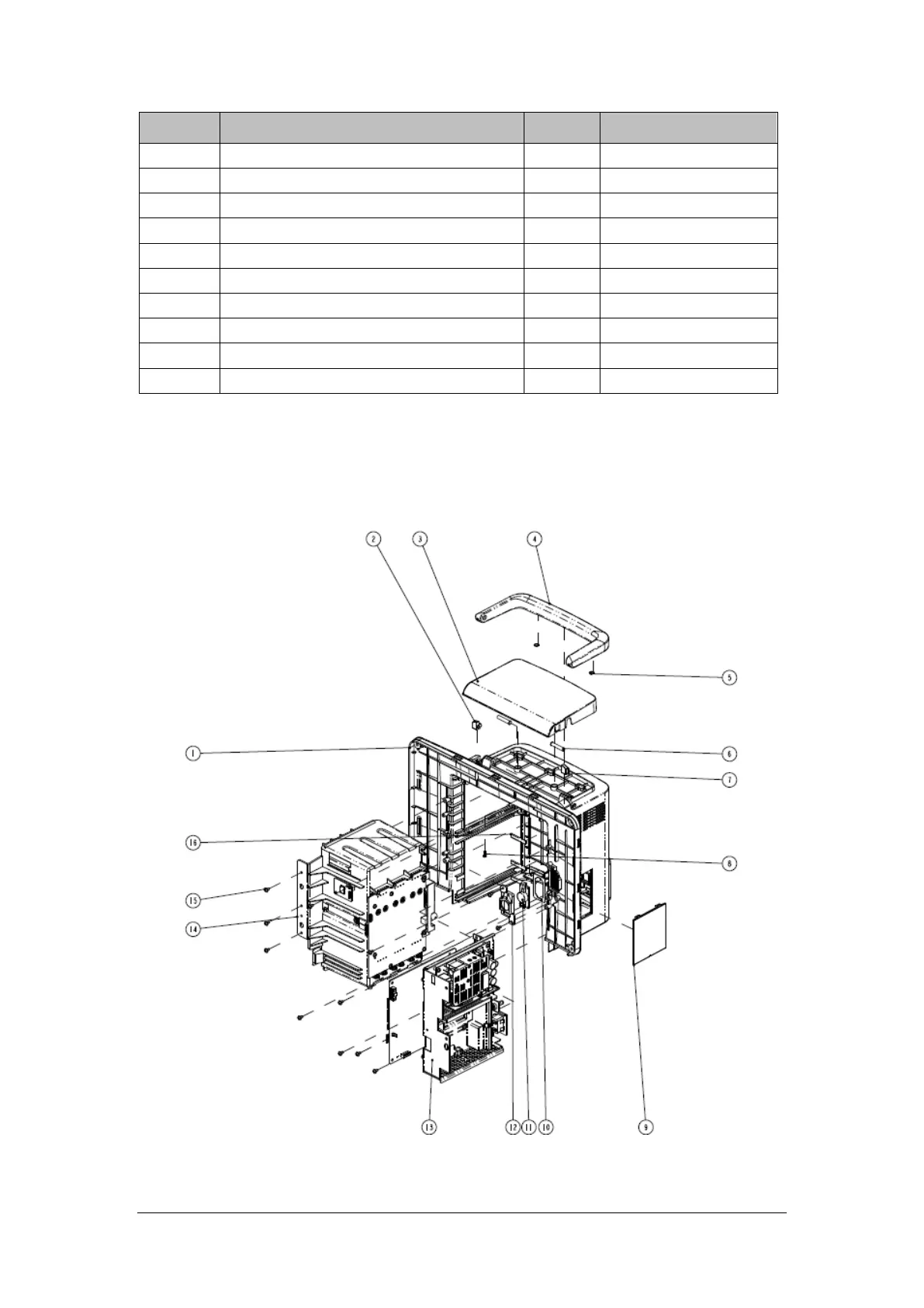
ITEM No. Description Qty FRU Part No.
6 Alarm LED and Light Sensor Board PCBA 1 051-002693-00
7 Cross recessed pan head screws,PT3X8 4 /
8 N15N17 front shell plate cable 1 009-006736-00*
9 CORE O.D=21.5mmI.D=9.5mm 1 1 /
10 N15 Mainboard to LCD cable (Sharp) 1 009-006407-00*
11 N15N17 touch screen cable (Sharp) 1 009-006730-00*
12 Power Switch and Indicate LED Board PCBA 1 051-002711-00
13 MK power button (P+R) 1 043-007956-01
14 Conductive cloth pad 0.08m /
15 Earth plate (N15-Sharp) 1 042-018592-00*
*: included in No.1 N15-Sharp front housing assembly (FRU) (115-044545-00)
7.2.4 N15 Rear Housing
7.2.4.1 Exploded View