Structure and Assembly/Disassembly 9-31
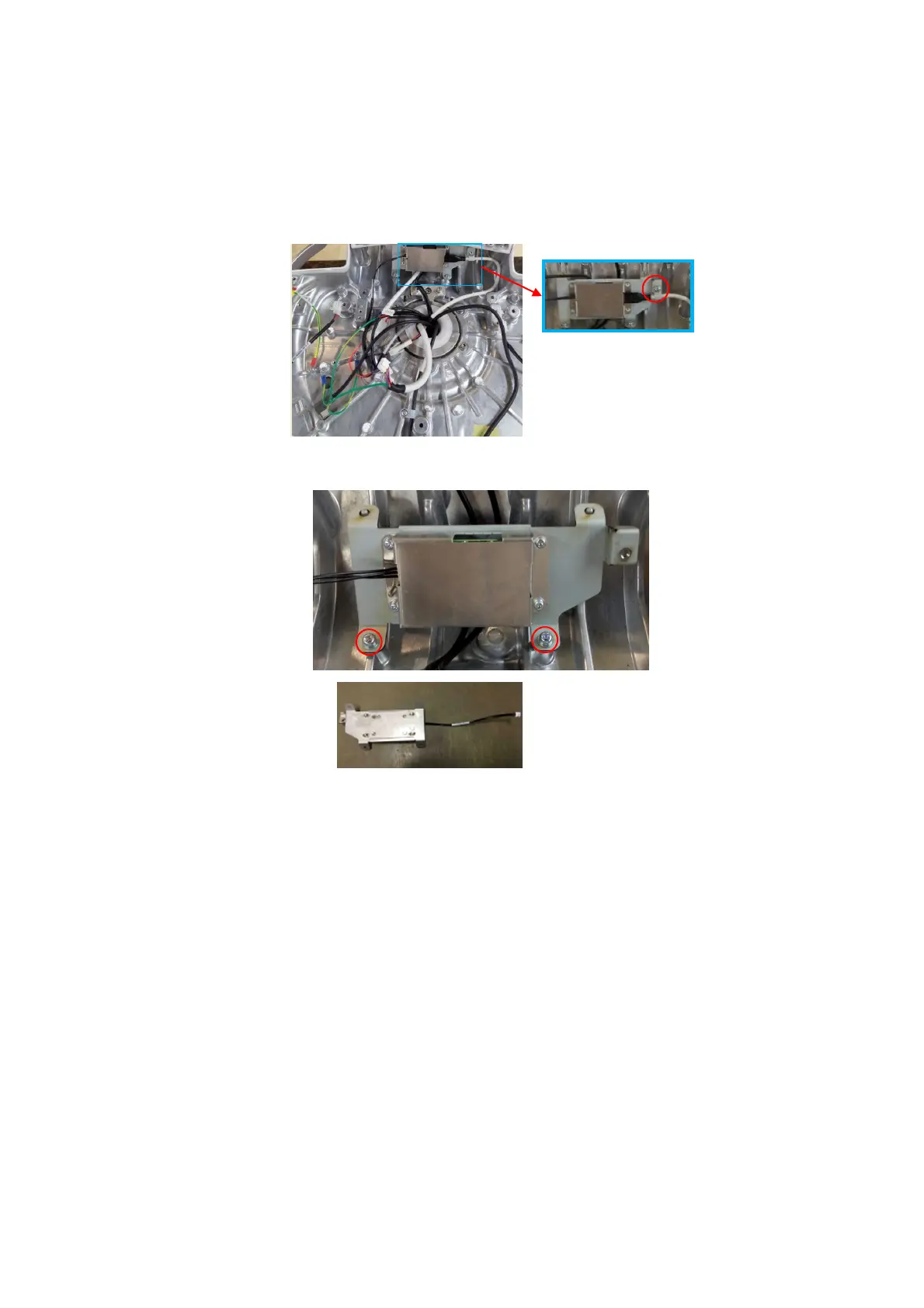
9.3.13 LCD Signal Connector PCBA assembly
1. Refer to 9.3.6 Control Panel Assembly for details.
2. Unscrew M4 X 12 cross panhead screw on UC-0.5 lock knob with screwdriver (M3, M4) to
remove the signal cable of the monitor.
3. Unscrew 2 M4 X12 cross panhead screws with screwdriver (M3, M4) to remove the LCD signal
connector PCBA assembly.
9.3.14 Support Arm Spanner/Bale of Wire for the
Monitor/Side Control Panel Base/Base Assembly
The disassembly tool: cross-headed screwdriver (M3, M4), inner hex spanner (M3, M5).
1. See Chapter 9.3.6, 9.3.8, 9.3.9, 9.3.10 and 9.3.12 for details.
2. Unscrew M4 X 12 cross panhead screw on UC-0.5 lock knob and UC-2 lock knob with
screwdriver (M3, M4), and unscrew one M4 X 12 cross panhead screw from the grounding
terminal of the monitor to remove the monitor cable and the rotating cap of the support arm.
LCD signal connector PCBA assembly

 Loading...