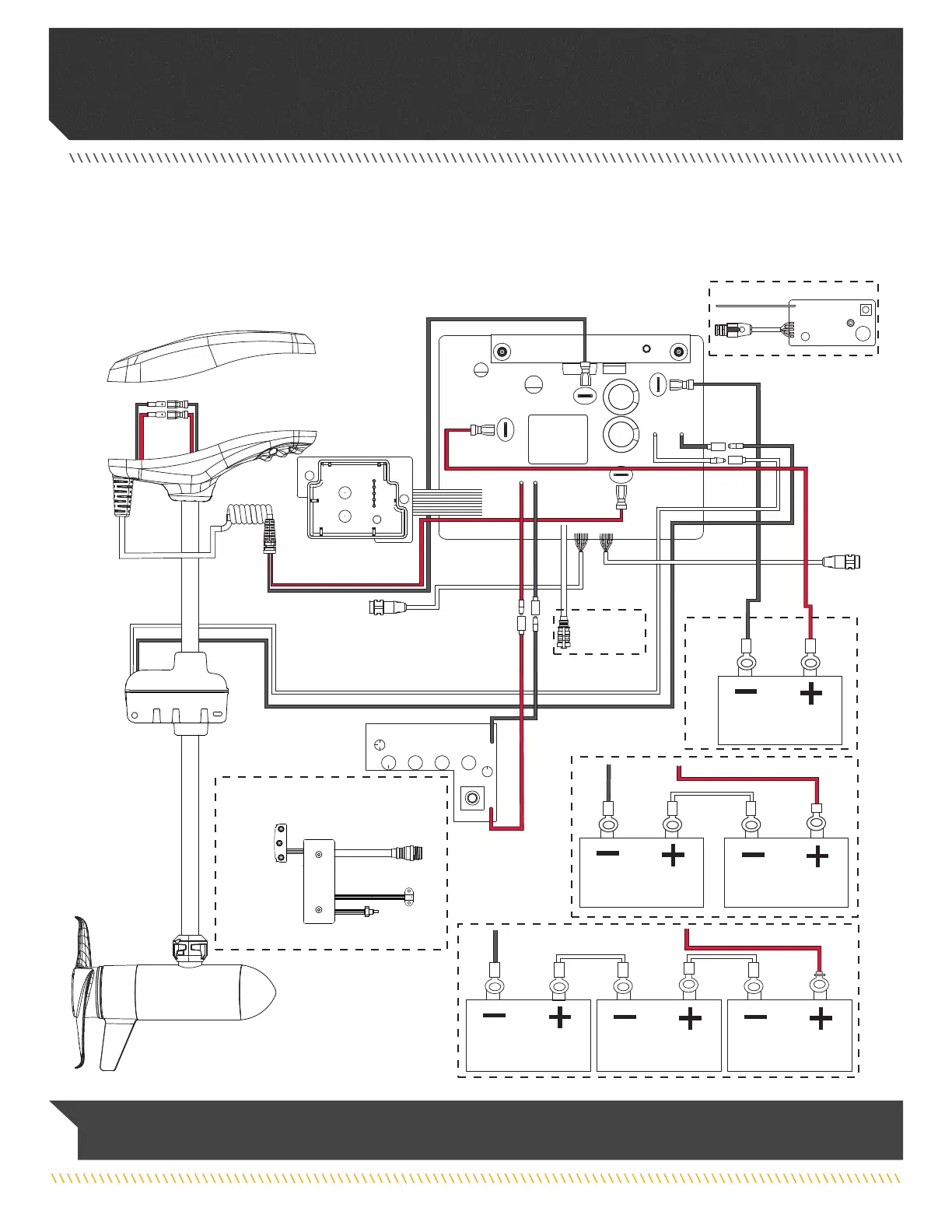
RIPTIDE TERROVA WITH COPILOT
The following Motor Wiring Diagram applies to all Riptide Terrova models that come factory installed with CoPilot. CoPilot or a Foot Pedal
may be installed as an after market accessory on select models.
Red M+
Red M+
Red M+
Black M-
Black M-
Black M-
Power Switch
Black B-
Black
Black
Black
White
White
Red B+
Red
Red
Black
Black
24v
36v
12v
Battery 1
Battery 1 Battery 2
Black B-
Red B+
Red B+
Black B-
Red B+
Battery 1
Battery 2 Battery 3
Foot Pedal
Spot-Lock Sensor
Speed Adjustment
Sensor
AutoPilot (Red)
Spot-Lock (Blue)
Constant
(Green)
Foot Pedal
Control Board
Foot Pedal
Attachment
Foot Pedal
Attachment
Battery
Gauge
Steering
Housing
Motor
Coil Cord
Accessory
Attachment
Accessory
Attachment
Control Head
CoPilot
CoPilot
Control
Board
NOTICE: This is a multi-voltage diagram. Double-check your motor's voltage for proper connections. Over-Current Protection
Devices are not shown in this illustration.
20 | minnkotamotors.com
©2022 Johnson Outdoors Marine Electronics, Inc.
MOTOR WIRING DIAGRAM