(2720)A 13
3256-22313256-2231
3256-22313256-2231
3256-2231
2782-12152782-1215
2782-12152782-1215
2782-1215
WhiteWhite
WhiteWhite
White
GrayGray
GrayGray
Gray
PinkPink
PinkPink
Pink
BlueBlue
BlueBlue
Blue
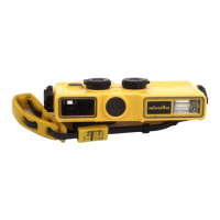
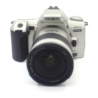
Fig.1 Installation of the assy cabi front.Fig.1 Installation of the assy cabi front.
Fig.1 Installation of the assy cabi front.Fig.1 Installation of the assy cabi front.
Fig.1 Installation of the assy cabi front.
1. Stick 2782-1215 onto 3256-2231 as shown on the figure.1. Stick 2782-1215 onto 3256-2231 as shown on the figure.
1. Stick 2782-1215 onto 3256-2231 as shown on the figure.1. Stick 2782-1215 onto 3256-2231 as shown on the figure.
1. Stick 2782-1215 onto 3256-2231 as shown on the figure.
2. Arrange the FPC of the zoom encoder FPC assy as shown on the figure.2. Arrange the FPC of the zoom encoder FPC assy as shown on the figure.
2. Arrange the FPC of the zoom encoder FPC assy as shown on the figure.2. Arrange the FPC of the zoom encoder FPC assy as shown on the figure.
2. Arrange the FPC of the zoom encoder FPC assy as shown on the figure.
FPC of the zoom encoder FPC assyFPC of the zoom encoder FPC assy
FPC of the zoom encoder FPC assyFPC of the zoom encoder FPC assy
FPC of the zoom encoder FPC assy
Stick the center and turn up to the front and the back.Stick the center and turn up to the front and the back.
Stick the center and turn up to the front and the back.Stick the center and turn up to the front and the back.
Stick the center and turn up to the front and the back.
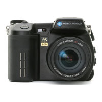
Fig.2 Installation of the EVF UNIT part, the strobo part and the holder battery partFig.2 Installation of the EVF UNIT part, the strobo part and the holder battery part
Fig.2 Installation of the EVF UNIT part, the strobo part and the holder battery partFig.2 Installation of the EVF UNIT part, the strobo part and the holder battery part
Fig.2 Installation of the EVF UNIT part, the strobo part and the holder battery part
1. Arrange the lead wire of the compl reflector as shown on the figure, and solder it to the compl PWB ST-1.1. Arrange the lead wire of the compl reflector as shown on the figure, and solder it to the compl PWB ST-1.
1. Arrange the lead wire of the compl reflector as shown on the figure, and solder it to the compl PWB ST-1.1. Arrange the lead wire of the compl reflector as shown on the figure, and solder it to the compl PWB ST-1.
1. Arrange the lead wire of the compl reflector as shown on the figure, and solder it to the compl PWB ST-1.
Compl reflectorCompl reflector
Compl reflectorCompl reflector
Compl reflector
Compl PWB ST-1Compl PWB ST-1
Compl PWB ST-1Compl PWB ST-1
Compl PWB ST-1
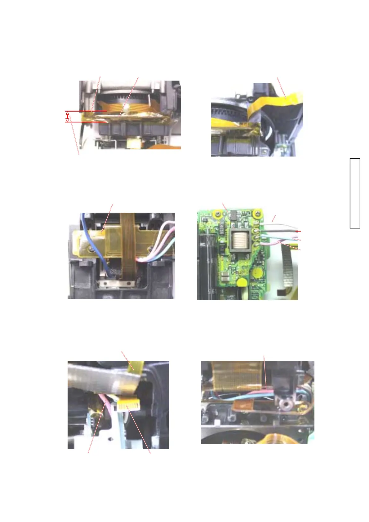
2. Make a set of the lens block, the EVF UNIT and the strobo part to install onto the assy cabi front. 2. Make a set of the lens block, the EVF UNIT and the strobo part to install onto the assy cabi front.
2. Make a set of the lens block, the EVF UNIT and the strobo part to install onto the assy cabi front. 2. Make a set of the lens block, the EVF UNIT and the strobo part to install onto the assy cabi front.
2. Make a set of the lens block, the EVF UNIT and the strobo part to install onto the assy cabi front.
3. Install the lead wire and FPC as shown on the figure.3. Install the lead wire and FPC as shown on the figure.
3. Install the lead wire and FPC as shown on the figure.3. Install the lead wire and FPC as shown on the figure.
3. Install the lead wire and FPC as shown on the figure.
Assy flexible PWB EVFAssy flexible PWB EVF
Assy flexible PWB EVFAssy flexible PWB EVF
Assy flexible PWB EVF
Lead wireLead wire
Lead wireLead wire
Lead wire
Lead wireLead wire
Lead wireLead wire
Lead wire
FPC of the zoom encoder FPC assyFPC of the zoom encoder FPC assy
FPC of the zoom encoder FPC assyFPC of the zoom encoder FPC assy
FPC of the zoom encoder FPC assy