34 (2720)A
REPAIR GUIDE
2. FIRMWARE2. FIRMWARE
2. FIRMWARE2. FIRMWARE
2. FIRMWARE
1. START1. START
1. START1. START
1. START
5. CCD AORI5. CCD AORI
5. CCD AORI5. CCD AORI
5. CCD AORI
7. CONTROL No.7. CONTROL No.
7. CONTROL No.7. CONTROL No.
7. CONTROL No.
8. BOOT MODE8. BOOT MODE
8. BOOT MODE8. BOOT MODE
8. BOOT MODE
10. CAMERA LOG READ10. CAMERA LOG READ
10. CAMERA LOG READ10. CAMERA LOG READ
10. CAMERA LOG READ
11. CAMERA LOG CLEAR11. CAMERA LOG CLEAR
11. CAMERA LOG CLEAR11. CAMERA LOG CLEAR
11. CAMERA LOG CLEAR
12. END12. END
12. END12. END
12. END
9. DESTINATION9. DESTINATION
9. DESTINATION9. DESTINATION
9. DESTINATION
6. READ ADJ-DATA6. READ ADJ-DATA
6. READ ADJ-DATA6. READ ADJ-DATA
6. READ ADJ-DATA
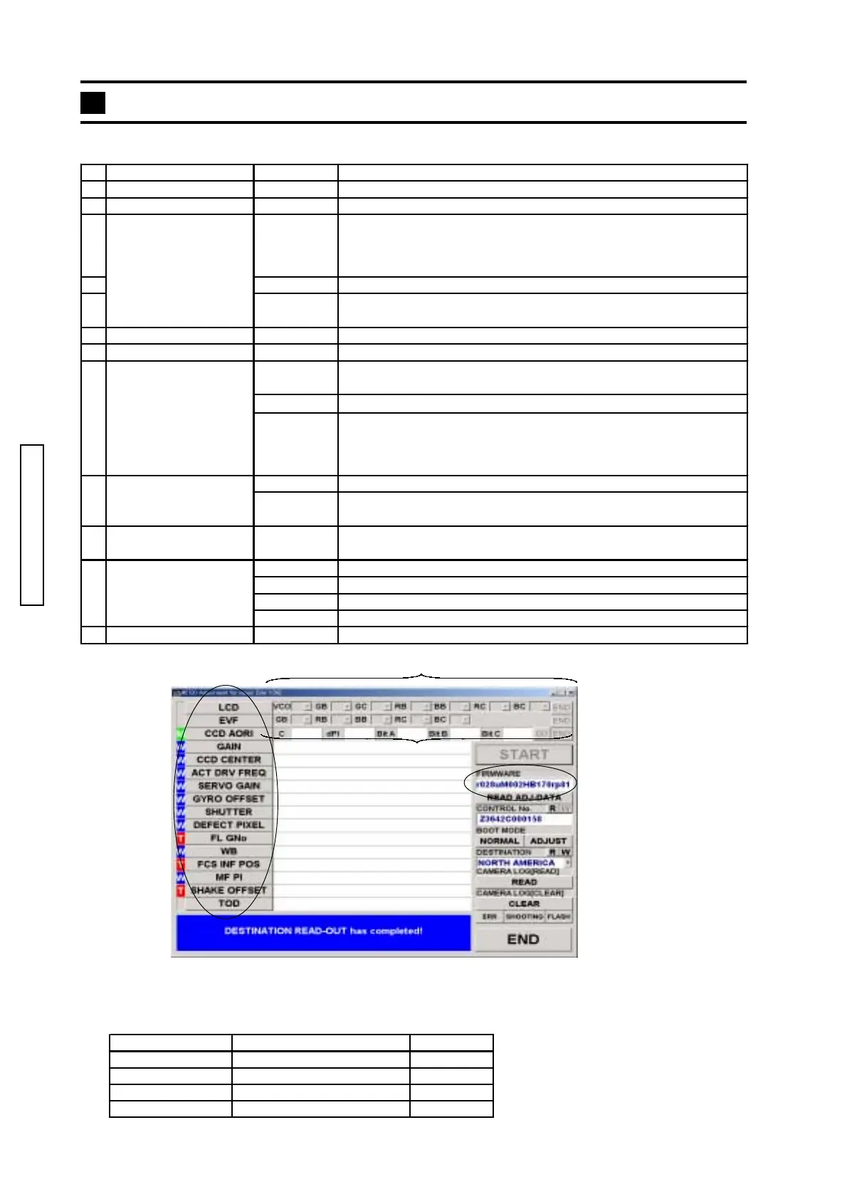
Contents of the adjustment program and CPU version readout
Contents of adjustment program
CPU version readout
1. Start 2720 Adjustment program. (See pg.33)
"FIRMWARE VERSION READ-OUThas completed!" is displayed.
2. Check the firmware in the adjustment program..
EachEach
EachEach
Each
adjustmentadjustment
adjustmentadjustment
adjustment
itemitem
itemitem
item
4. LCD/EVF4. LCD/EVF
4. LCD/EVF4. LCD/EVF
4. LCD/EVF
FIRMWARE Item Sample
1 - 5 th Main CPU version r028u
6 - 9 th Camera CPU version M002
10 - 14 th Anti shake CPU version HB170
15 - 18 th Adjustment DLL rp81
Item Sub item Operation/Display
1. START Connecting 2720 adjustment program.
2. FIRMWARE
Displaying CPU version when the adjustment program is launched.
3.
Starting of each adjustmnet.
Supplied service parts "DM-1 Compl. PWB" (0492) will be shipped after
being adjusted. So the LCD adjustment and EVF adjustment are not
necessary.
4. LCD/EVF
Optional adjustments of LCD by changing values.
5. CCD AORI
Optional adjustments of CCD AORI.
(C, dPI, Bit B, Bit C) (See pg. 38.)
6. READ ADJ-DATA The adjustment value of each adjustment item is displayed.
7. CONTROL No. R Disabled
Camera setting mode for the case when the connection between
camera and 2782 adjustment program
NORMAL Normal mode
ADJUST
Adjustment mode:
In this case, it is not necessary to press function button, digital effect
button, and AEL button at once. Be sure to return to normal mode after
completing all the adjustments.
R Distination check mode.
W
Distination setting mode. Selectable destinations: JAPAN/NORTH
AMERICA/EUROPE/CHINA
10. CAMERA LOG READ ALL
Read the log of the error code, number of release, and number of
flash burst. (See pg.2 of Trouble-shooting chart)
ALL
Clear the log of error code, number of release, and number of flash burst.
ERR Clear the error code log.
SHOOTING Clear the shutter-release log.
FLASH Clear the flash burst log.
12. END Break connection
11. CAMERA LOG CLEAR
Each adjustment item
8. BOOT MODE
9. DISTINATION