10 (20)
The Buzzer and LED Indicators
3.1.14 BATTERY TROUBLE LED
3.1.15 GROUND FAULT LED
3.1.16 SYSTEM RESET LED
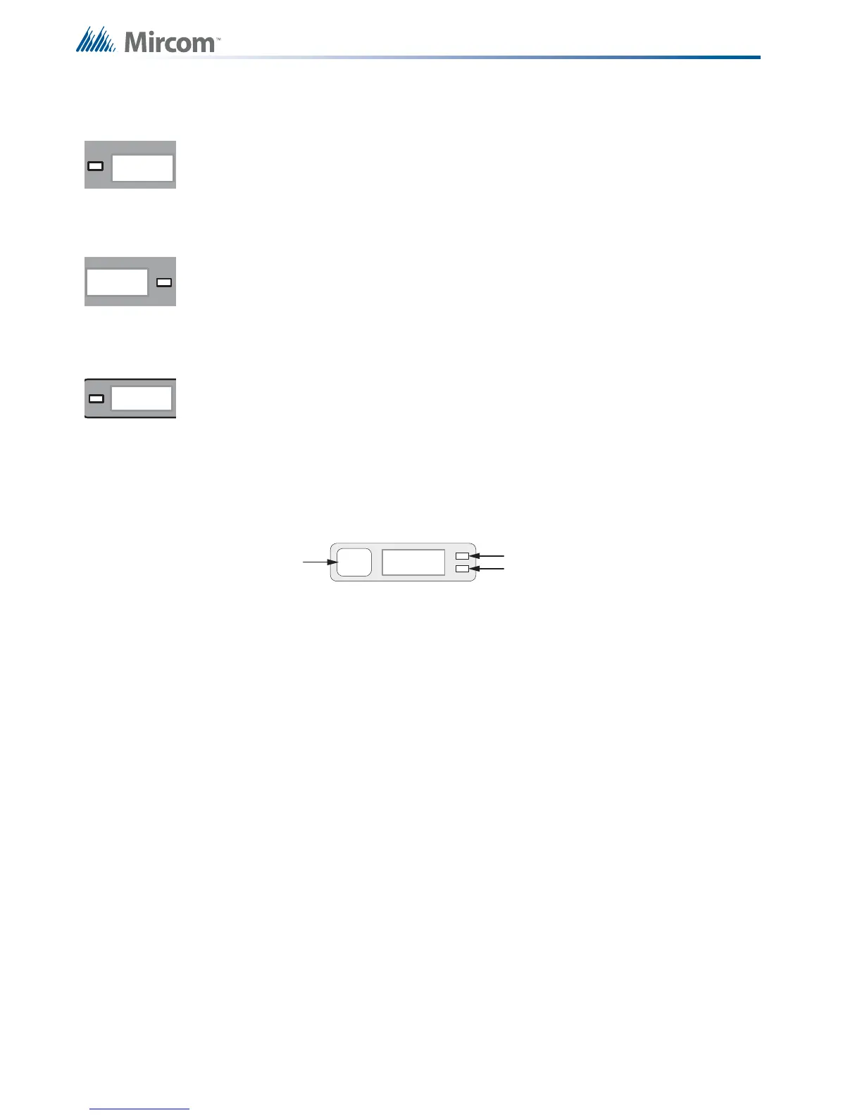
3.2 Indicating Circuit Indicators
The panel has 1 indicator for each of the 12 initiating circuits (shown in Figure 1). Each
indicator has a button and 2 LEDs, shown in Figure 2.
Figure 2 Alarm Circuit Indicator
The Circuit Disconnect Button is described in 5.0 Circuit (Zone) Disconnect Buttons on
page 16. The LEDs are described below.
The amber BATTERY TROUBLE LED flashes at the trouble rate when the battery is either
low or disconnected.
The amber GROUND FAULT LED flashes at the trouble rate when the ground fault detector
detects a ground fault on any field wiring. It turns off when the ground fault is cleared.
The amber SYSTEM RESET LED illuminates for a short time when the SYSTEM RESET
button is pressed.
ZONE-1
DISCO NNECT
Circuit Status LED
Circuit Trouble LED
Circuit
Disconnect
Button

 Loading...


