6 (20)
2.0 Main Display
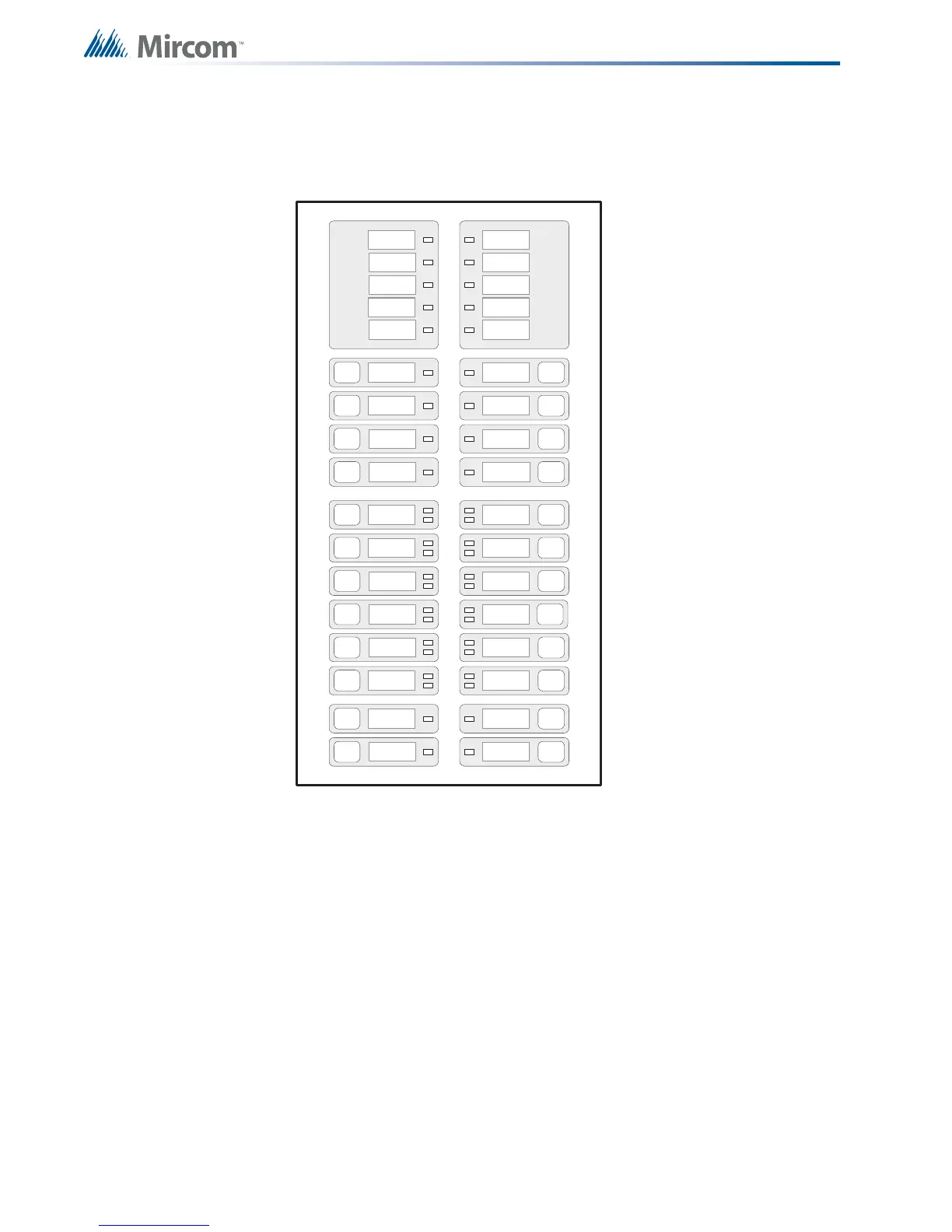
Refer to the diagram below for the LED indicators and control buttons locations.
Figure 1 Main Display
The main display panel on the main fire alarm control board consists of:
• 18 common LED indicators (top half of display)
• 8 common buttons (top half of display)
• Up to 12 Initiating circuit alarm LEDs and 12 initiating circuit trouble LED indicators
• 4 indicating circuit LEDs (labeled NAC - Notifying Appliance Circuit)
• Up to 16 disconnect buttons (12 for initiating circuit and 4 for indicating circuits)
LED indicators may be amber, red, or green, and may illuminate continuously (steady), or at
one of two flash rates:
• Fast flash (supervisory): 120 flashes per minute
• Trouble flash (trouble): 20 flashes per minute
WALK
TEST
REMOTE
TROUBLE
CPU FAIL
GRO UND
FAULT
SIGNAL
SILENCE
FIRE
DRILL
GENERAL
ALARM
SYSTEM
RESET
AUX
DISCO NNE CT
LAMP
TEST (MENU)
A.C.
ON
COMMON
ALARM
COMMON
SUPV
COMMON
TROUBLE
BATTERY
TROUBLE
ZONE-1
DISCO NNE CT
ZONE-3
DISCO NNE CT
ZONE-5
DISCO NNE CT
ZONE-7
DISCO NNE CT
ZONE-9
DISCO NNE CT
ZONE-11
DISCO NNE CT
ZONE-2
DISCO NNE CT
ZONE-4
DISCO NNE CT
ZONE-6
DISCO NNE CT
ZONE-8
DISCO NNE CT
ZONE-10
DISCO NNE CT
ZONE-12
DISCO NNE CT
NAC-1
DISCO NNE CT
NAC-3
DISCO NNE CT
NAC-2
DISCO NNE CT
NAC-4
DISCO NNE CT
AUTOMATIC
ALARM SIGNAL
CANCEL
ALM/SUP/TBL/BLDG
AUDIBLE SIL

 Loading...


