68
Configuration with the CFG-300 LCD Service Tool
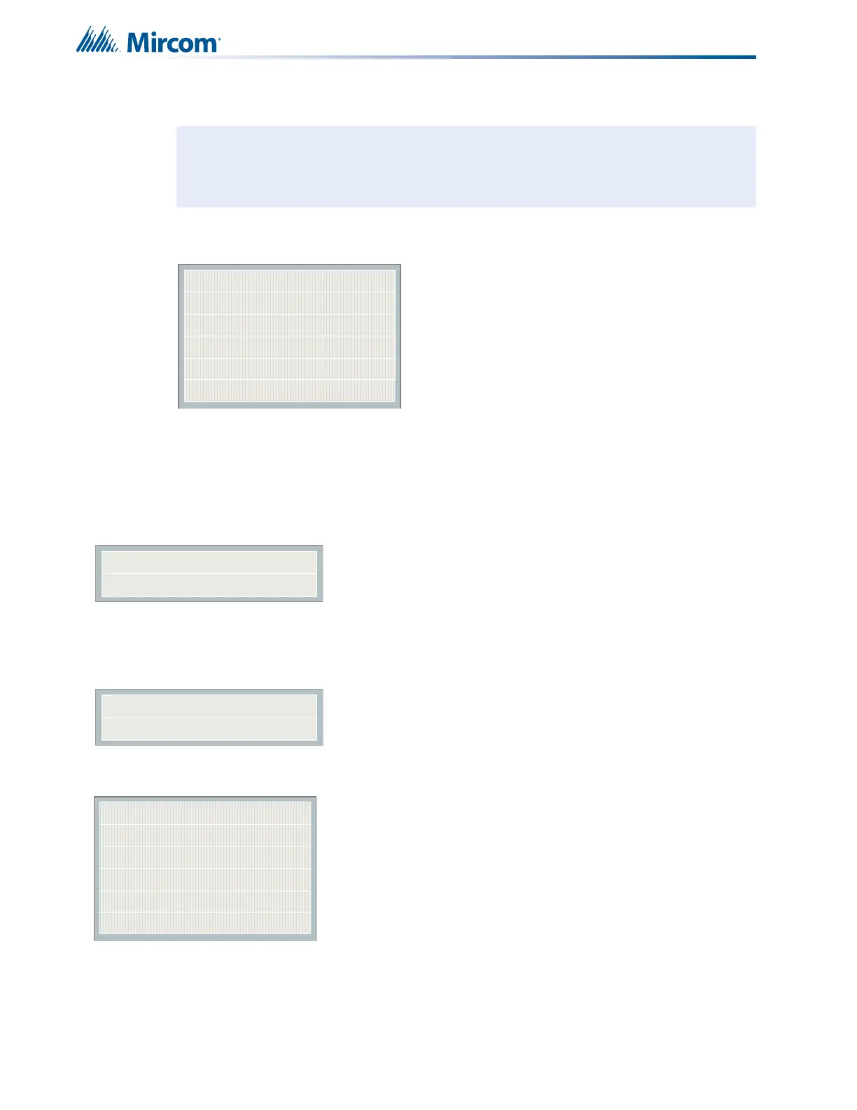
11.3.2 Command Menu/FA-300 Config-->Inp Zone
This Inp Zone menu is used to program the process type for the initiating circuits. The
maximum number of initiating circuits is 12. Only those supported by the particular model are
shown in the CFG-300 Configuration Tool.
11.3.3 Command Menu/FA-300 Config-->I3 Zone
Note: Refer to 11.2.1 Using the Keypad to Program the FA-300 on page 61 for detailed
instructions on making menu selections.
Command Menu/FA-300 Config/Ipt. Zone
1.Process Type (Initiating circuit)
|
|
|
12.
[X] NON-VERIF ALARM
->Default
[ ] VERIF ALARM
[ ] SPRKL ALM
[ ] WTR-FLOW ALM
[ ] NON-LATCH SUP
[ ] LATCH SUPV
[ ] GEN ALARM
[ ] BUILDING
[ ] TRB ONLY
Use this menu to select the
circuit type of each input
zone. See 9.7 Circuit
Types on page 50.
[ ] Zone-1->Default
.
.
.
[ ] Zone-12->Default
Use this menu if i
3
devices
are present on a zone. See
10.2 System Sensor’s i3
Devices on page 56.
1 Zone-1
2 Zone-2
--
--
Initiating Zone
12 Zone12
Zone-1 Type
[X] NON-VERIF ALARM
Zone-12 Type
[X] NON-VERIF ALARM
[ ] Zone-1
[ ] Zone-2
--
--
I3 Detection Zones
[ ] Zone-12