69
Configuration with the CFG-300 LCD Service Tool
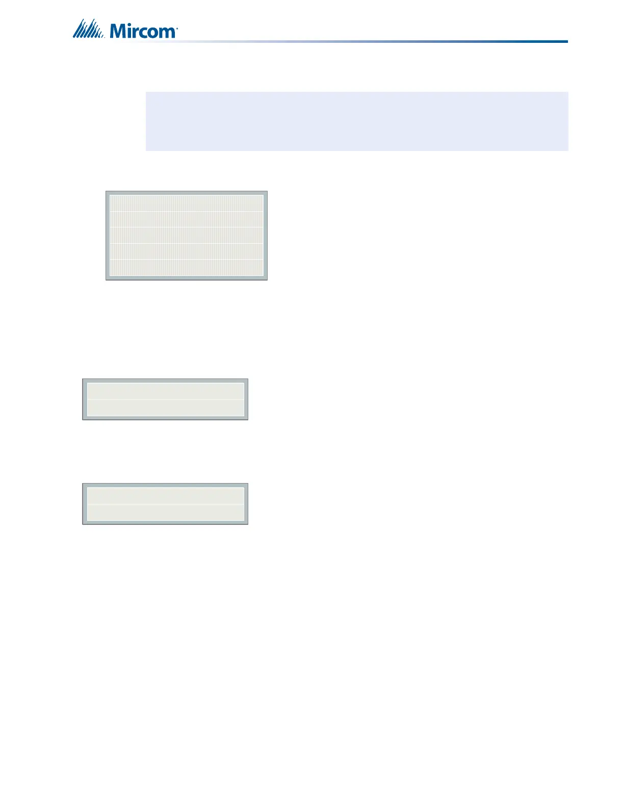
11.3.4 Command Menu/FA-300 Config-->Opt Zone
This menu is used to program the process type of the indicating circuits. The maximum
number of indicating circuits is 4. Only those supported by the particular model are shown in
the CFG-300 Configuration Tool.
Note: Refer to 11.2.1 Using the Keypad to Program the FA-300 on page 61 for detailed
instructions on making menu selections.
Command Menu/FA-300 Config/Opt. Zone
1.Process Type (Indicating Circuits)
|
|
|
4.
[X] SIL-ABLE->Default
[ ] NON SIL-ABLE
[ ] SIL-ABLE STR
[ ] NON-SIL STR
Use this menu to program
the process type of each
indicating circuit. See 9.8
Indicating (Signal) Circuit
Types on page 52.
1 NAC-1
2 NAC-2
3 NAC-3
4 NAC-4
Indicating Zone
 Loading...


