120
8575
8575
N/B Maintenance
N/B Maintenance
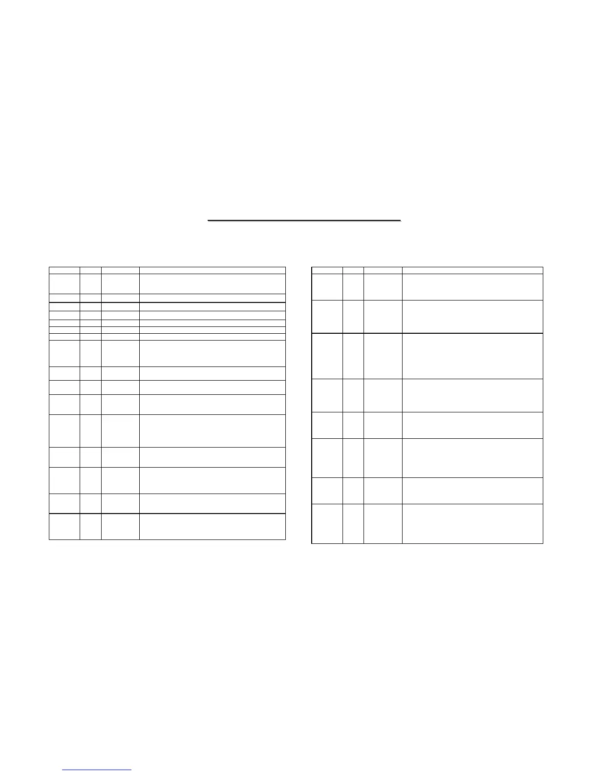
5.4 SiS301LV / Chrontel CH7019 TV/LVDS Encoder
Pin # Type Symbol Description
2 Analog
LPLLCAP LVDS PLL Capacitor
This pins allows coupling of any signal to the on-chip loop
filter capacitor.
5,24 Out
LL2C,LL1C Positive LVDS differential Clock2 & Clock1
6,25 Out
LL2C*,LL1C* Negative LVDS differential Clock2 & Clock1
8,11,14,17 Out
LDC[7:4] Positive LVDS differential data[7:4]
9,12,15,18 Out
LDC[7:4]* Negative LVDS differential data[7:4]
21,27,30,33 Out
LDC[3:0] Positive LVDS differential data[3:0]
22,28,31,34 Out
LDC[3:0]* Negative LVDS differential data [3:0]
38 Analog
ISET Current Set Resistor Input
This pin sets the DAC current. A 140-ohm resistor should be
connected between this pin and DAC_GND (pin 39) using
short and wide traces.
40,42,44,46 Out
DACB[3:0] DAC Output B
Video Digital-to-Analog outputs.
41,43,45,47 Out
DACA[3:0] DAC Output A
Video Digital-to-Analog outputs.
120 Out
VOUT V-Sync Output
This pin is the output of a voltage translating digital buffer and
is driven from V5V.
110 In
VIN V-Sync Input
This pin is the input of a voltage translating digital buffer.
Input threshold can be programmed by serial port to equal to
VREF2/2 or to DVDD/2. The amplitude will be 0 to VDDV.
VREF1 is the threshold level for these inputs.
119 Out
HOUT H-Sync Output
This pin is the output of a voltage translating digital buffer and
is driven from V5V.
109 In
HIN H-Sync Input
This pin is the input of a voltage translating digital buffer.
Input threshold can be programmed by serial port to equal to
VREF2/2 or to DVDD/2.
49 Out
C/HSYNC Composite / Horizontal Sync
Provides composite sync in TV modes and horizontal sync in
bypass RGB mode. This pin is driven by the DVDD supply.
50 Out
BCO/VSYNC Buffered Clock Outputs / Vertical Sync
This output pin provides buffered crystal oscillator clock
output or VSYNC output in bypass RGB mode. This pin is
driven by the DVDD supply.
Pin # Type Symbol Description
52 In
XI/FIN Crystal Input / External Reference Input
A parallel resonant 14.31818MHz crystal (+ 20 ppm) should
be attached between this pin and XO. However, an external
CMOS compatible clock can drive the XI/FIN input.
53 Out
XO Crystal Output
A parallel resonance 14.31818MHz crystal (+ 20 ppm)
should be attached between this pin and XI / FIN. However,
if an external CMOS clock is attached to XI/FIN, XO should
be left open.
59 Out
P-OUT Pixel Clock Output
This pin provides a pixel clock signal to the VGA controller
which can be used as a reference frequency. The output is
selectable between 1X and 2X of the pixel clock frequency.
The output driver is driven from the VDDV supply (pin 60).
This output has a programmable tri-state. The capacitive
loading on this pin should be kept to a minimum.
61 In
VREF1 Reference Voltage Input 1
The VREF1 pin inputs a reference voltage of VDDV / 2.
The signal is derived externally through a resistor divider
and decoupling capacitor, and will be used as a reference
level for data, sync and clock inputs.
68-73,77-82 In
D1[11:0] Data1[11] through Data1[0] Inputs
These pins accept the 12 data inputs from a digital video
port of a graphics controller. The levels are 0 to VDDV.
VREF1 is the threshold level.
76,74 In
XCLK1
XCLK1*
External Clock Inputs
These inputs form a differential clock signal input to the
device for use with the H1, V1 and D1[11:0] data. If
differential clocks are not available, the XCLK1* input
should be connected to VREF1. The clock polarity can be
selected by the MCP1 control bit.
85-90,94-99 In
D2[11:0] Data2[11] through Data2[0] Inputs
These pins accept the 12 data inputs from a digital video
port of a graphics controller. The levels are 0 to DVDDV.
VREF1 is the threshold level.
93,91 In
XCLK
XCLK2*
External Clock Inputs
These inputs form a differential clock signal input to the
device for use with the H2, V2 and D2[11:0] data. If
differential clocks are not available, the XCLK2* input
should be connected to VREF1. The clock
polarity can be selected by the MCP2 control bit.