108
8575
8575
N/B Maintenance
N/B Maintenance
Host BUS Interface Continue
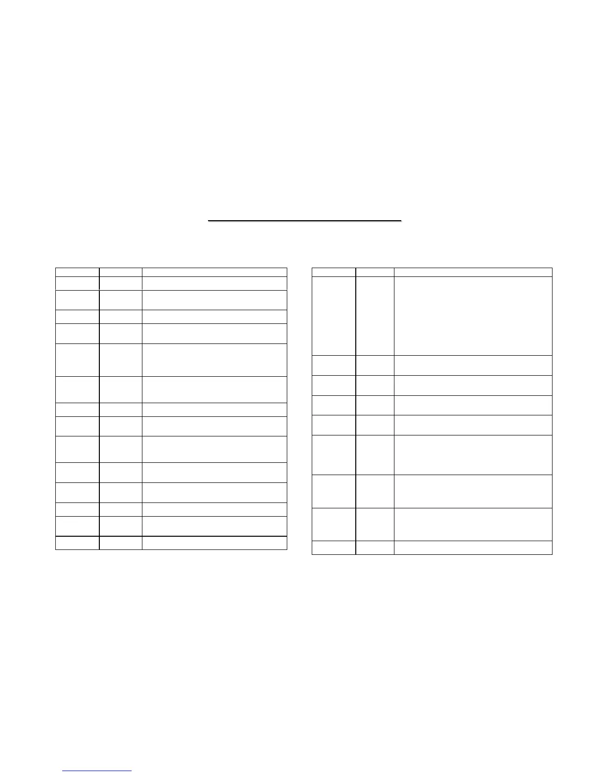
Name Pin Attr Signal Description
RS[2:0]#
O
1.2~1.85V – M
Response Status:
RS[2:0]# are driven by the response agent to indicate the transaction
response type. The following shows the response type.
RS[2:0] Response
000 Idle State
001 Retry
010 Defer
011 Reserved
100 Reserved
101 No data
110 Implicit Write-back
111 Normal Data
HTRDY#
O
1.2~1.85V – M
Target Ready:
During write cycles, response agent will drive TRDY# to indicate it
is ready to accept data.
DRDY#
I/O
1.2~1.85V – M
Data Ready:
DRDY# is driven by the bus owner whenever the data is valid on
the bus.
DBSY#
I/O
1.2~1.85V – M
Data Bus Busy:
Whenever the data is not valid on the bus with DRDY# is deserted,
DBSY# deasserted to hold the bus.
HD[63:0]#
I/O
1.2~1.85V – M
Data Bus Busy:
Whenever the data is not valid on the bus with DRDY# is deserted,
DBSY# deasserted to hold the bus.
DBI[3:0]#
I/O
1.2~1.85V – M
Dynamic Bus Inversion: An active DBI# will invert
it’s corresponding data group signals.
DBI0# is referenced by HD[15:0],
DBI1# is referenced by HD[31:16]
DBI2# is referenced by HD[47:32]
DBI3# is referenced by HD[63:48]
HDSTBP[3:0]#
I/O
1.2~1.85V – M
Source synchronous data strobe used to latch data at falling edge
HD[15:0], DBI0# are latched by HDSTBP0#
HD[31:16], DBI1# are latched by HDSTBP1#
HD[47:32], DBI2# are latched by HDSTBP2#
HD[63:48], DBI3# are latched by HDSTBP3#
HDSTBN[3:0]#
I/O
1.2~1.85V– M
Source synchronous data strobe used to latch data at falling edge
HD[15:0], DBI0# are latched by HDSTBN0#
HD[31:16], DBI1# are latched by HDSTBN1#
HD[47:32], DBI2# are latched by HDSTBN2#
HD[63:48], DBI3# are latched by HDSTBN3#
HNCOMP
I
M
GTL N-MOS Compensation Input
Host BUS Interface
Name Pin Attr Signal Description
CPUCLK
CPUCLK#
I
0.71V – M
Host differential clock input.
CPURST#
O
1.2~1.85V – M
Host Bus Reset:
CPURST# is used to keep all the bus agents in
the same initial state before valid cycles issued.
CPUPWRGD#
CPUPWRGD# is used to inform CPU that main power is
stable
ADS#
I/O
1.2~1.85V – M
Address Strobe :
Address Strobe is driven by CPU or SiS650 to indicate the
start of a CPU bus cycle.
HADSTB[1:0]#
1.2~1.85V – M
Source synchronous address strobe used to latch
HREQ[4:0]# & HA[31:3]# at both falling and rising edge.
HREQ[4:0]# & HA[16:3]# are latched by
HASTB0#
HA[31:17] are latched by HASTB1#
HREQ[4:0]#
I/O
1.2~1.85V – M
Request Command:
HREQ[4:0]# are used to define each transaction type during
the clock when ADS# is asserted and the clock after ADS# is
asserted.
HA[31:3]#
I/O
1.2~1.85V – M
Host Address Bus
BREQ0#
O
1.2~1.85V – M
Symmetric Agent Bus Request:
BREQ0# is driven by the symmetric agent to request for the
bus.
BPRI#
O
1.2~1.85V – M
Priority Agent Bus Request:
BPRI# is driven by the priority agent that wants to request the
bus.
BPRI# has higher priority than BREQ0# to access a bus.
BNR#
I/O
1.2~1.85V – M
Block Next Request:
This signal can be driven asserted by any bus agent to block
further requests being pipelined.
HLOCK#
I
1.2~1.85V – M
Host Lock :
CPU asserts HLOCK# to indicate the current bus cycle is
locked.
HIT#
I/O
1.2~1.85V – M
Keeping a Non-Modified Cache Line
HITM#
I/O
1.2~1.85V – M
Hits a Modified Cache Line:
Hit Modified indicates the snoop cycle hits a modified line in
the L1/L2 cache of CPU.
DEFER#
O
1.2~1.85V – M
Defer Transaction Completion: