8 SYSTEM APPLICATION EXAMPLES
8-126 Application Example 2
8.2.2 System configuration
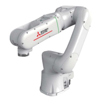
Robot system 1 detects "human approach" and "human presence" as follows.
"Human presence" is detected by safety sensor 1A (such as a light curtain).
"Human approach" is detected by safety sensor 1B (such as a safety switch (door), laser scanner, and safety
mat).
Robot system 2 detects "human approach" and "human presence" as follows.
"Human presence" is detected by safety sensor 2A (such as a light curtain).
"Human approach" is detected by safety sensor 2B (such as a safety switch (door), laser scanner, and safety
mat).
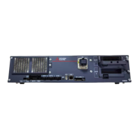
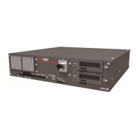
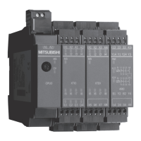
Construct a safety system with the following CC-Link IE TSN devices.
Table 8-10 Safety system components
(station No.0)
[RnSFCPU-SET]
Safety CPU module
[RnSFCPU]
Safety function module
[R6SFM]
Master/local module
[RJ71GN11-T2]
Remote station
(station No.1)
Safety remote I/O module
[NZ2GNSS2-16DTE]
Remote station
(station No.2)
Safety remote I/O module
[NZ2GNSS2-16DTE]
(station No.3)
Programmable controller CPU module
[RnCPU]
Robot CPU module
[R16RTCPU]
Master/local module
[RJ71GN11-T2]
(station No.4)
Programmable controller CPU module
[RnCPU]
Robot CPU module
[R16RTCPU]
Master/local module
[RJ71GN11-T2]
* Connect devices to the safety inputs of the safety remote I/O module (Item No.2) as follows: safety sensor 1A
to the safety inputs X0 and X1, safety sensor 1B to the safety inputs X2 and X3, and emergency stop switch 1
to the safety inputs X4 and X5.
* Connect devices to the safety inputs of the safety remote I/O module (Item No.3) as follows: safety sensor 2A
to the safety inputs X0 and X1, safety sensor 2B to the safety inputs X2 and X3, and emergency stop switch 2
to the safety inputs X4 and X5.
* The programmable controller CPU module does not perform safety communication (standard communication
possible).
* The safety IO process uses the safety remote I/O module's double input discrepancy detection function, input
dark test function (test pulses), and input response time setting function (filters for noise and chattering).

 Loading...
