3 CONNECTIONS AND COMMUNICATION DESTINATION SETTINGS
3-12 System Configurations and Connections
3. CONNECTIONS AND COMMUNICATION DESTINATION
SETTINGS
This chapter explains system configurations, safety programmable controller settings at the communication
destination, network settings, and other settings to use this function.
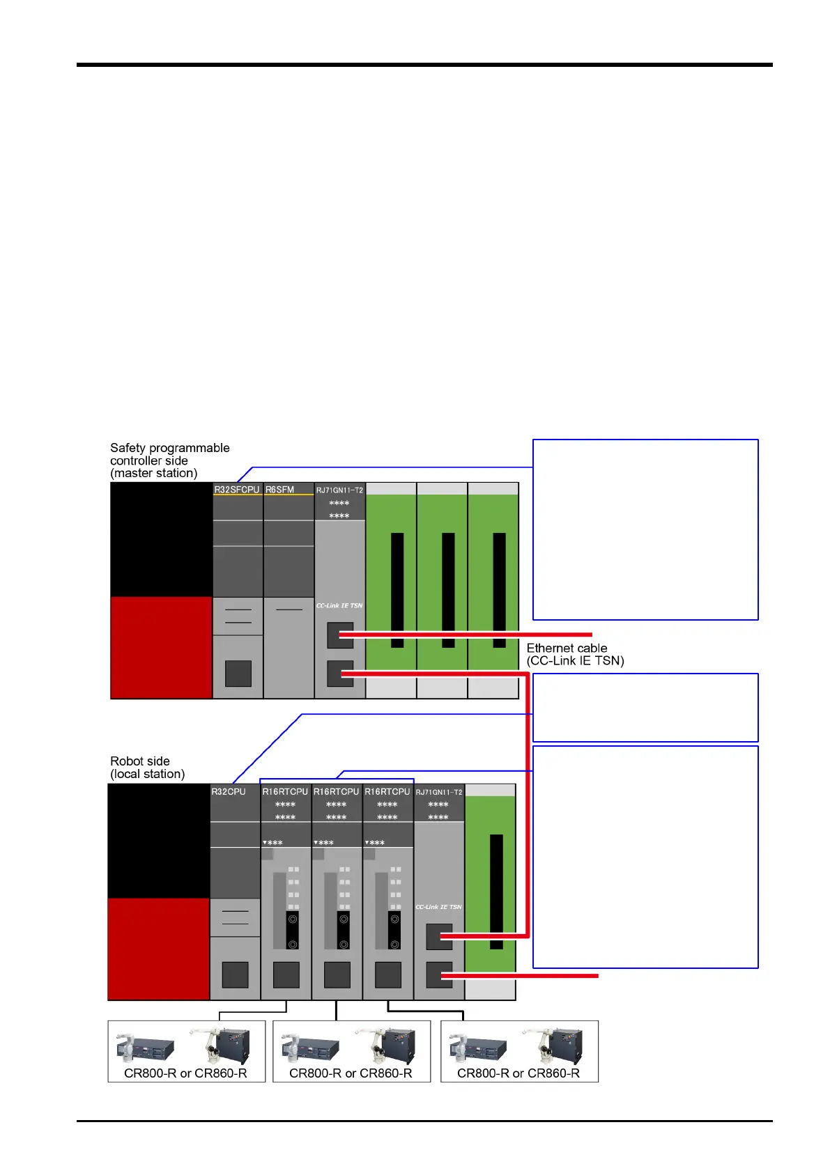
3.1 System Configurations and Connections
Connect the safety programmable controller-side master/local module (master station) and the robot-side
master/local module (local station) using an Ethernet cable. The system configurations are shown in "3.1.1 Robot-
side system configuration" and "3.1.2 Safety programmable controller-side system configuration". External safety
I/O devices, such as light curtains and laser scanners, can be connected using MELSEC iQ-R series safety remote
I/O modules (remote stations).
For information on CC-Link IE TSN connections, network configurations, safety remote I/O modules, and MELSEC
iQ-R series module configurations, refer to the following manuals.
□ MELSEC iQ-R CC-Link IE TSN User's Manual (Startup) (SH-082127ENG)
□ MELSEC iQ-R CC-Link IE TSN User's Manual (Application) (SH-082129ENG)
□ CC-Link IE TSN Remote I/O Module (With Safety Functions) User's Manual (SH-082227ENG)
□ MELSEC iQ-R Module Configuration Manual (SH-081262ENG)
Fig. 3-1: Set-up
Settings
>3.2
Safety Communication Settings
(Safety Programmable
Controller Side)
>3.3
Creating a Safety Program
Settings
>3.2
Startup and Basic Configuration
>4.2
Defining 3D Models
>4.3
Safety Logic Edit
>4.4
Safety Monitoring Functions
>4.5
 Loading...


