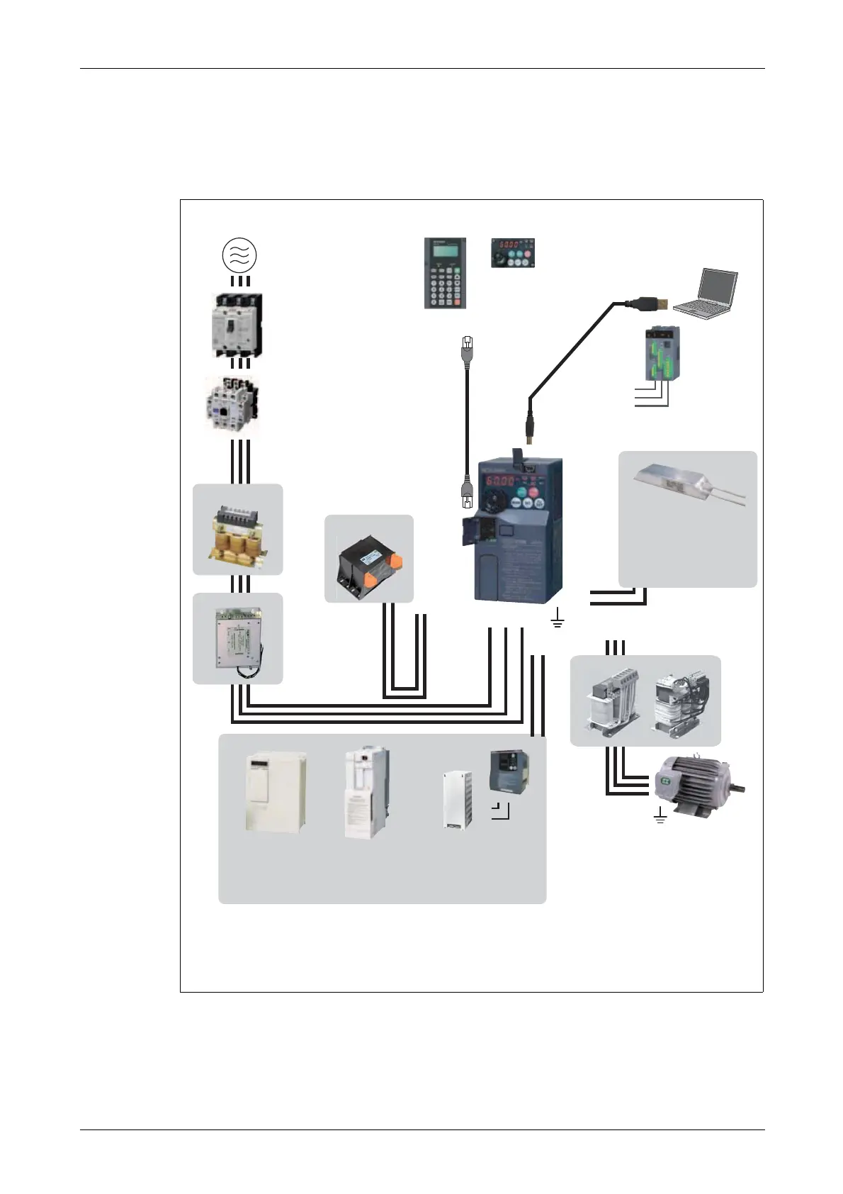
Fig. 3-1: System configuration overview
AC power supply
Use within the permissible power supply
specifications of the inverter. To ensure safety,
use a moulded case circuit breaker, earth
leakage circuit breaker or magnetic contactor
to switch power ON/OFF.
(Refer to Appendix A.)
Moulded case circuit breaker (MCCB)
or earth leakage circuit breaker (ELB),
fuse
The breaker must be selected carefully
since an in-rush current flows in the
inverter at power on.
(Refer to section 3.1.1.)
AC reactor
(FR-BAL-B)
DC reactor
(FFR-HEL-(H)-E)
EMC filter
(FFR-CS / FFR-MSH)
(optional)
Install this as required.
High power factor
converter (FR-HC)
Power supply harmonics can
be greatly suppressed. Install
this as required.
Power regeneration
common converter
(FR-CV)
Greater braking capability
is obtained.
Install this as required.
Resistor unit (FR-BR)
Discharging resistor
(GZG, GRZG)
The regenerative braking
capability of the inverter can
be exhibited fully.
Install this as required.
Brake unit
(FR-BU2/BU-UFS)
Magnetic contactor (MC)
Install the magnetic contactor to ensure
safety. Do not use this magnetic
contactor to start and stop the inverter.
Doing so will cause the inverter life to be
shorten.
(Refer to section 3.1.1.)
Enclosure surface
operation panel
(FR-PA07)
By connecting the con-
nection cable
(FR-A5CBL) to the PU
connector, operation
can be performed from
FR-PU07 or FR-PA07.
FFR-DT = Output filter
FFR-SI = Sine wave filter
Earth
Earth
Devices connected to the output
Do not install a power factor correction
capacitor, surge suppressor, arrester or radio
noise filter on the output side of the inverter.
When installing a moulded case circuit
breaker on the output side of the inverter,
contact each manufacturer for selection of
the moulded case circuit breaker.
Earth
To prevent an electric shock, always earth
the motor and inverter.
USB connector
A personal computer can be
connected with a USB
(Ver. 1.1) cable.
Brake resistor (FR-ABR)
Braking capability can be
improved. (FR-E720S-030SC or
more, FR-E740-016SC or more).
Install this as required. Always
install a thermal relay when using
a brake resistor whose capacity is
11K or more.
Reactor (FR-BAL-B, FFR-HEL-(H)-E)
Reactors (option) should be used when power harmonics measures are taken, the power
factor is to be improved or the inverter is installed near a large power supply system
(500kVA or more). The inverter may be damaged if you do not use reactors.
Select the reactor according to the model. Remove the jumpers across terminals P/+
and P1 to connect to the DC reactor. (Refer to section 3.7.6).
Parameter unit
FR-PU07
Inverter (FR-E700SC EC)
Approved safety
relay module
Required for
compliance with
safety standard.
 Loading...