Main circuit connection Wiring
3 - 6
3.3 Main circuit connection
3.3.1 Specification of main circuit terminals
When using single-phase power input, terminals are L1, N.
Indicated as "+" on the terminal block of the single-phase power input model.
Indicated as "–" on the terminal block of the single-phase power input model.
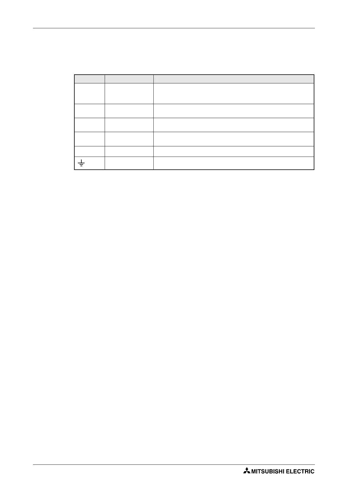
Terminal Name Description
R/L1,
S/L2,
T/L3
AC power input Connect to the commercial power supply.
Keep these terminals open when using the high power factor converter (FR-HC) or
power regeneration common converter (FR-CV).
U, V, W Inverter output Voltage ouput of the inverter
(3~, 0V–power supply voltage, 0.2–400Hz)
P/+
, PR
Brake resistor
connection
Connect a brake resistor (FR-ABR) across terminals P/+ and PR.
(The brake resistor can not be connected to the FR-E720S-008SC and 015SC.)
P/+
, N/–
Brake unit connection Connect the brake unit (FR-BU2), power regeneration common converter (FR-CV)
or high power factor converter (FR-HC).
P/+
, P1
DC reactor connection Remove the jumper across terminals P/+ and P1 and connect a DC reactor.
PE For earthing the inverter chassis. Must be earthed.
Tab. 3-2: Specification of main circuit terminal
 Loading...