Connection of stand-alone option units Wiring
3 - 40
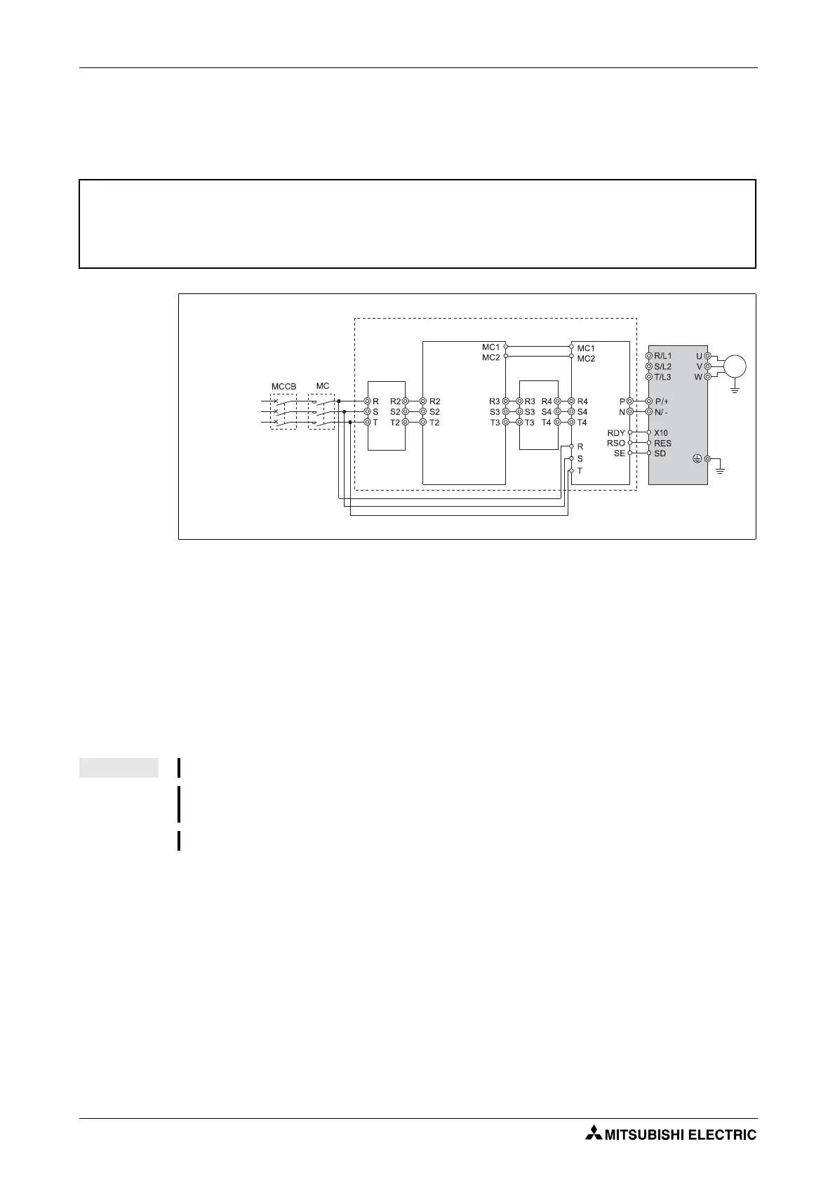
3.7.4 Connection of the high power factor converter FR-HC
When connecting the high power factor converter (FR-HC) to suppress power harmonics, perform
wiring securely as shown below.
Keep input terminals (R/L1, S/L2, T/L3) open. Incorrect connection will damage the inverter.
Do not insert an MCCB between the terminals P/+ and N/− (between P and P/+, between N and
N/−). Opposite polarity of terminals N/−, P/+ will damage the inverter.
Use Pr. 178 to Pr. 184 "Input terminal function selection" to assign the terminals used for the X10,
RES signal. (Refer to section 6.10).
Be sure to connect terminal RDY of the FR-HC to the X10 signal or MRS signal assigned terminal
of the inverter, and connect terminal SE of the FR-HC to terminal SD of the inverter. Without proper
connecting, FR-HC will be damaged.
b
CAUTION:
Perform wiring of the high power factor converter (FR-HC) securely as shown below. Incorrect
connection will damage the high power factor converter and inverter.
I002060E
Fig. 3-32: Connection of the high power factor converter FR-HC
NOTES The voltage phases of terminals R/L1, S/L2, T/L3 and terminals R4, S4, T4 must be matched.
Use sink logic when the FR-HC is connected. The FR-HC cannot be connected when source logic
(factory setting) is selected.
Do not remove a jumper across terminal P/+ and P1 except when connecting a DC reactor.
3-phase AC
power supply
Inverter
High power factor
converter (FR-HC)
Reactor 1
(FR-HCL01)
External box
(FR-HCB)
Motor
M
3~
Phase
detection
Reactor 2
(FR-HCL02)
 Loading...