Wiring Connection of stand-alone option units
FR-E700SC EC 3 - 37
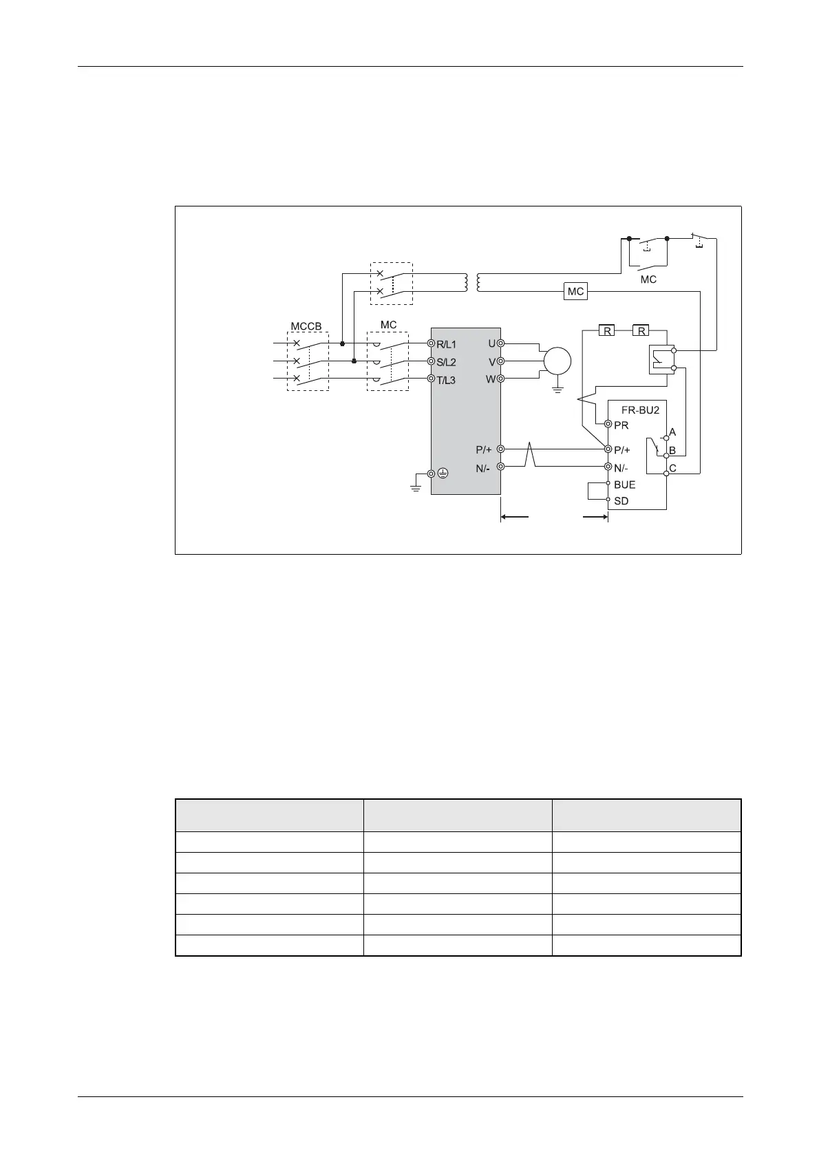
3.7.3 Connection of a brake unit FR-BU2
When connecting a brake unit to improve the brake capability at deceleration, make connection as
shown below.
Connection example with the GRZG type discharging resistor
If the control contacts are only specified for 230V control power you must install a transformer
when using a 400V power supply.
Connect the inverter terminals (P/+, N/−) and brake unit terminals so that their terminal signals
match with each other. (Incorrect connection will damage the inverter.)
The wiring distance between the inverter, brake unit and resistor unit should be within 5m. If
twisted wires are used, the distance should be within 10m.
If the transistors in the brake unit should become faulty, the resistor can be unusually hot, causing
a fire. Therefore, install a magnetic contactor on the inverters input side to configure a circuit so
that a current is shut off in case of fault.
Refer to FR-BU2 manual for connection method of discharging resistor.
I002044E
Fig. 3-30: Connection with the brake unit FR-BU2
Brake Unit Discharging Resistor
Recommended External Thermal
Relay
FR-BU2-1.5K GZG 300W-50Ω (one) TH-N20CXHZKP-1.3A
FR-BU2-3.7K GRZG 200-10Ω (three in series) TH-N20CXHZKP-3.6A
FR-BU2-7.5K GRZG 300-5Ω (four in series) on request
FR-BU2-15K GRZG 400-2Ω (six in series) on request
FR-BU2-7.5K GRZG 200-10Ω (six in series) TH-N20CXHZKP-3.6A
FR-BU2-15K GRZG 300-5Ω (eight in series) on request
Tab. 3-19: Recommended external relay
ON
3-phase AC
power supply
OFF
Inverter
≤ 5m
M
3~
Motor
T
Discharging
resistor
 Loading...