Parameter Communication operation and setting
FR-E700SC EC 6 - 227
6.19 Communication operation and setting
6.19.1 PU connector
Using the PU connector, you can perform communication operation from a personal computer etc.
When the PU connector is connected with a personal, FA or other computer by a communication ca-
ble, a user program can run and monitor the inverter or read and write to parameters.
Purpose Parameters that must be set
Refer to
Section
Communication operation from
PU connector
Initial setting of computer link
communication (PU connector)
Pr. 117–Pr. 124 6.19.2
Modbus-RTU communication
specification
Pr. 117, Pr. 118,
Pr. 120, Pr. 122,
Pr. 343, Pr. 502
Pr. 549
6.19.5
Restrictions on parameter write
through communication
Communication E²PROM write selection Pr. 342 6.19.3
Communication using USB
(FR Configurator)
USB communication Pr. 547, Pr. 548 6.19.6
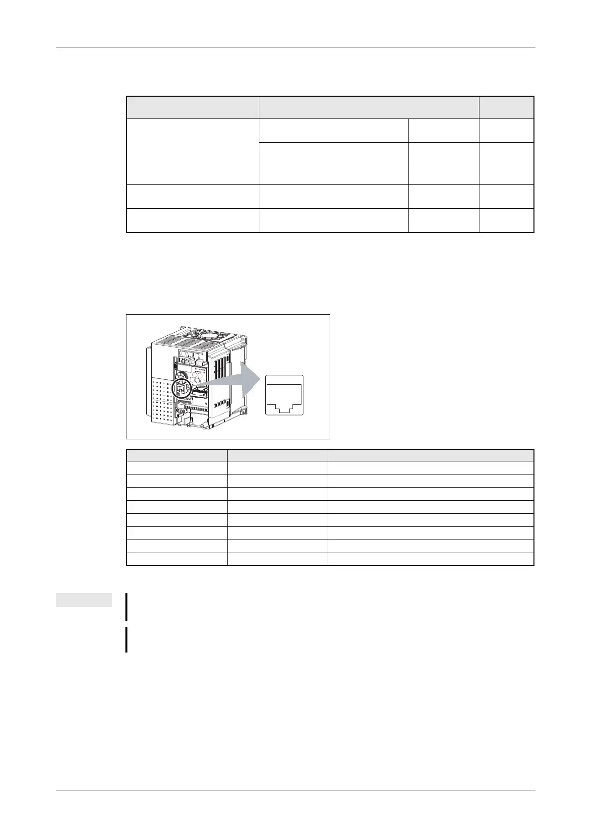
Fig. 6-109:
PU connector pin-outs
I001935E
Pin Number Name Description
1) SG Earth (Ground) (connected to terminal 5)
2) — Operation panel power supply
3) RDA Inverter receive+
4) SDB Inverter send−
5) SDA Inverter send+
6) RDB Inverter receive−
7) SG Earth (Ground) (connected to terminal 5
8) — Operation panel power supply
Tab. 6-66: PU connector (terminal description)
NOTES
Pins No. 2) and 8) provide power to the operation panel or parameter unit. Do not use these pins
for RS-485 communication.
Do not connect the PU connector to the computer's LAN board, FAX modem socket or telephone
modular connector. The product could be damaged due to differences in electrical specifications.
 Loading...