11. OPTIONS AND AUXILIARY EQUIPMENT
11 - 37
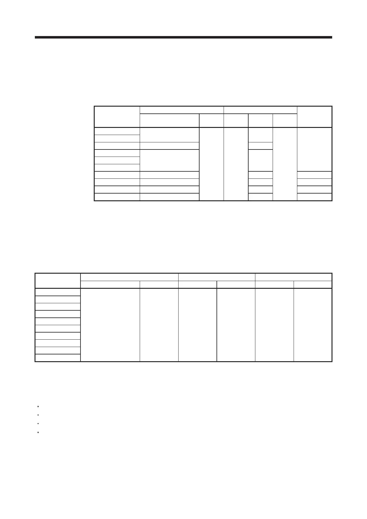
11.10 Molded case circuit breakers, fuses, magnetic contactors (recommended)
(1) For main circuit power supply
Always use one molded case circuit breaker and one magnetic contactor with one servo amplifier. When
using a fuse instead of the molded case circuit breaker, use the one having the specifications given in
this section.
Molded case circuit breaker (Note 1) Fuse
Servo amplifier
Frame, rated current
Voltage
AC [V]
Class
Current
[A]
Voltage
AC [V]
Magnetic
contactor
(MC) (Note 2)
MR-J4-10A
MR-J4-20A
30 A frame 5 A 10
MR-J4-40A 30 A frame 10 A 15
MR-J4-60A
MR-J4-70A
MR-J4-100A
30 A frame 15 A 20
S-N10
MR-J4-200A 30 A frame 20 A 40 S-N18
MR-J4-350A 30 A frame 30 A 70 S-N20
MR-J4-500A 50 A frame 50 A 125 S-N35
MR-J4-700A 100 A frame 75 A
240 T
150
300
S-N50
Note 1.
2.
When using the servo amplifier as a UL/CSA standard compliant product, refer to appendix 5.
Use a magnetic contactor with an operation delay time (interval between current being applied to
the coil until closure of contacts) of 80 ms or less.
(2) For control circuit power supply
When the wiring for the control circuit power supply (L11, L21) is thinner than that for the main circuit
power supply (L1, L2, L3), install an overcurrent protection device (molded case circuit breaker or fuse)
to protect the branch circuit.
Molded case circuit breaker (Note) Fuse (Class T) Fuse (Class K5)
Servo amplifier
Frame, rated current Voltage AC [V] Current [A] Voltage AC [V] Current [A] Voltage AC [V]
MR-J4-10A
MR-J4-20A
MR-J4-40A
MR-J4-60A
MR-J4-70A
MR-J4-100A
30 A frame 5 A 240 1 300 1 250
MR-J4-200A
MR-J4-350A
MR-J4-500A
MR-J4-700A
Note. When using the servo amplifier as a UL/CSA standard compliant product, refer to appendix 5.
11.11 Power factor improving DC reactors
The following shows the advantages of using power factor improving DC reactor.
It improves the power factor by increasing the form factor of the servo amplifier's input current.
It decreases the power supply capacity.
The input power factor is improved to be about 85%.
As compared to the power factor improving AC reactor (FR-HAL), it decreases the loss.
When connecting the power factor improving DC reactor to the servo amplifier, always disconnect P3 and
P4. If it remains connected, the effect of the power factor improving DC reactor is not produced.
When used, the power factor improving DC reactor generates heat. To release heat, therefore, leave a 10
cm or more clearance at each of the top and bottom, and a 5 cm or more clearance on each side.

 Loading...


