3. SIGNALS AND WIRING
3 - 5
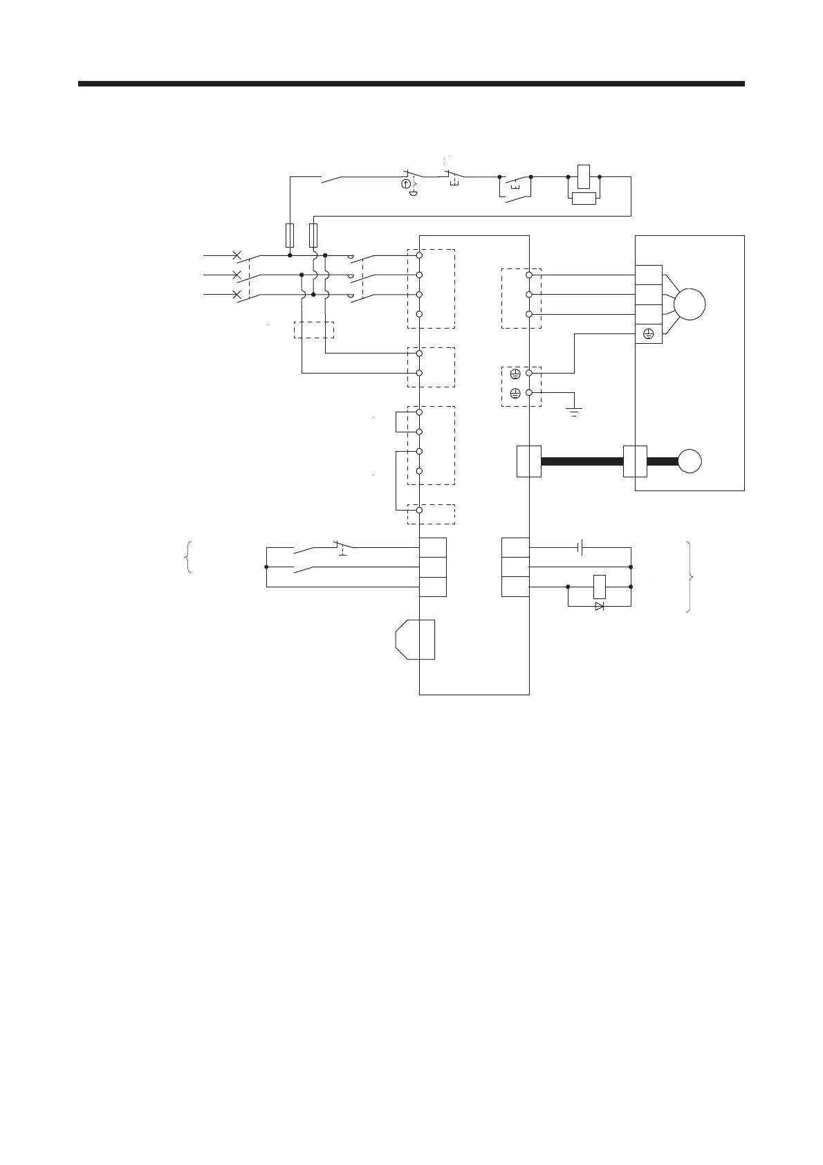
(3) MR-J4-500A
MC(ᵈ6)
ALM
DICOM
DOCOM
CN3
DC24V
RA1
L1
L2
L3
⋧
AC200V㨪240V
ࠨࡏࠕࡦࡊ
L11
L21
P3
C
N-
P+
P4
U
V
W
TE1
TE4
PE
TE3
TE2
ࠨࡏࡕ࠲
U
V
W
M
ࡕ࠲
ࠛࡦࠦ࠳
CN2
(ᵈ3)
ࠛࡦࠦ࠳
ࠤࡉ࡞
(ᵈ5)
ࠝࡈ
MC
ࠝࡦ
MC
SK
㕖Ᏹᱛࠬࠗ࠶࠴
CN8
(ᵈ8)
⍴⛊ࠦࡀࠢ࠲
(ࠨࡏࠕࡦࡊߦઃዻ)
MCCB
D
TE4
(ᵈ1)
(ᵈ2)
(ᵈ9)
㓚
RA1
(ᵈ4)
㓚
CN1
ᒝᱛ2
ࠨࡏࠝࡦ
(ᵈ4)
EM2
SON
DOCOM
(ᵈ7)
࿁〝㔚Ḯ
Note 1.
2.
3.
4.
5.
6.
7.
8.
9.
Always connect between P3 and P4 terminals. (factory-wired) When using the power factor improving DC reactor,
refer to section 11.11. Use either the power factor improving DC reactor or the power factor improving AC reactor.
Always connect between P+ and D terminals. (factory-wired) When using the regenerative option, refer to section
11.2.
For the encoder cable, use of the option cable is recommended. For selecting cables, refer to Servo Motor Instruction
Manual (Vol. 3).
This diagram is for sink I/O interface. For source I/O interface, refer to section 3.9.3.
For connecting servo motor power wires, refer to Servo Motor Instruction Manual (Vol. 3).
Use a magnetic contactor with an operation delay time (interval between current being applied to the coil until closure
of contacts) of 80 ms or less. Depending on the main circuit voltage and operation pattern, bus voltage decreases,
and that may cause the forced stop deceleration to shift to the dynamic brake deceleration. When dynamic brake
deceleration is not required, slow the time to turn off the magnetic contactor.
Configure up a circuit to turn off EM2 when the main circuit power is turned off to prevent an unexpected restart of the
servo amplifier.
When not using the STO function, attach a short-circuit connector supplied with a servo amplifier.
When wires used for L11 and L21 are thinner than wires used for L1, L2, and L3, use a molded case circuit breaker.
(Refer to section 11.10.)
24 V DC
Malfunction
Off
On
Servo motor
Motor
3-phase
200 V AC to 240V AC
MC (Note 6)
(Note 9)
Servo amplifier
(Note 5)
Encoder
(Note 3)
Encoder cable
(Note 1)
(Note 2)
Malfunction
(Note 4)
(Note 4)
Forced sto
2
Servo-on
(Note 7)
Main circuit
power supply
(Note 8)
Short-circuit connector
(Packed with the servo amplifier)
EMG stop switch

 Loading...


