1-3
Error no. L0031
1Error list
L0031 Error message Air pressure error
Cause This is a user setting error.
Measures Reset the error after releasing the cause.
H0039 Error message Door Switch Signal line is faulty.
Cause The one point of contact in 2 points of contact of the door switch has broken. Or wiring is not the double
lines.
Measures Turn off the power supply.
Confirm whether there is any problem in wiring of the switch. And, please confirm whether it is wiring of the
double line. Refer to the "Examples of safety measures" given in separate "Standard Specifications
Manual" for door switch wiring.
Turn on the power supply again after checking.
H0040 Error message Door Switch Signal is Input
Cause The door switch is open.
Measures Confirm whether the door switch input signal is connected correctly. And close the door connected to the
input signal of door switch.
H0041 * One of the errors below is detected.
Please take measures corresponding to an error message.
Error message Comm. error (Remote I/O #1).
Cause Communication line is illegal.
Measures Checks the remote I/O cable connection between the CPU and the drive unit in the CR7xx-Q controller.
Checks the communication cable is grounded correctly or connected correctly.
Error message The CRC error of remote I/O channel 1 occurs
Cause An error was found in the communication line for remote I/O channel 1.
Measures Checks the remote I/O cable connection between the CPU and the drive unit in the CR7xx-Q controller.
H0042 * Error message Comm. error (Remote I/O #2).
Cause Communication line is illegal.
Measures Checks the remote I/O cable connection in the CR750-Q/CR751-Q controller.
H0044 Error message OP Mode key line is faulty.
Cause The state of doubled line is not matching (OP Mode key line)
The state of doubled line is not matching (Key switch interface)
Wiring might be connected to reserved pins of exclusive input/output signals connectors.
This error may occur when the mode key switch of the operation panel is turned slowly.
Measures Turn off the power and confirm whether wiring of the key switch interface is right. Wiring needs to be dou
-
bled.
Check the wiring to the connectors of exclusive output signals is connected correctly.
Turn the power OFF and ON once. If it comes back, contact to your service provider.
H0045 Error message Faulty Line (T/B Enable Switch).
Cause The state of doubled line is not matching (T/B Enable Switch).
Measures Turn the power OFF and ON once. If it comes back, contact to your service provider.
H0046 Error message Faulty wiring (Enabling Device).
Cause The state of doubled wiring is not matching (Enabling Device).
Measures Turn off the power and confirm whether wiring of the switch is right. Wiring needs to be doubled. Refer to
the separate manual, "Standard Specifications Manual" for wiring of the door switch.
H0050 Error message EMG signal is input. (external)
Cause 1) The external emergency stop is being input.
If the emergency stop of T/B turns on, this error may occur simultaneously.
2) The fuse (4A fuse) installed at the bottom of the 24 V power supply circuit in the controller may have
blown out. For the fuse blowout, the emergency stop made by the customer may be the cause, or there
may be a ground fault or short circuit with the 24 V power supply in the wiring of a door switch, enabling
device, etc.
Measures 1) Release the external emergency stop signal.
2) Investigate and correct the ground fault or short circuit portion in the wiring made by the customer.
Then, replace the fuse inside the controller. Refer to Page 60, "Fig.2-3 : Fuse (F8) exchange place
(CR750/CR751 controller)" for details. (On details of the fuse, contact the manufacturer.)
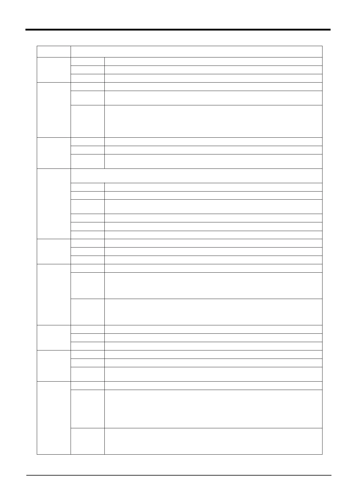
Error No. Error cause and measures
 Loading...