7 Buffer Memory
7.2 Buffer memory details
47
FX3U-64CCL User's Manual
1
Introduction
2
Specification
and function
3
System
Configuration
4
Installation
5
Wiring, Start-up
procedure
6
FX
3U
-64CCL
setting (switch
setting)
7
Buffer Memory
8
Program
Example
9
Troubleshooting
A
Version
Information
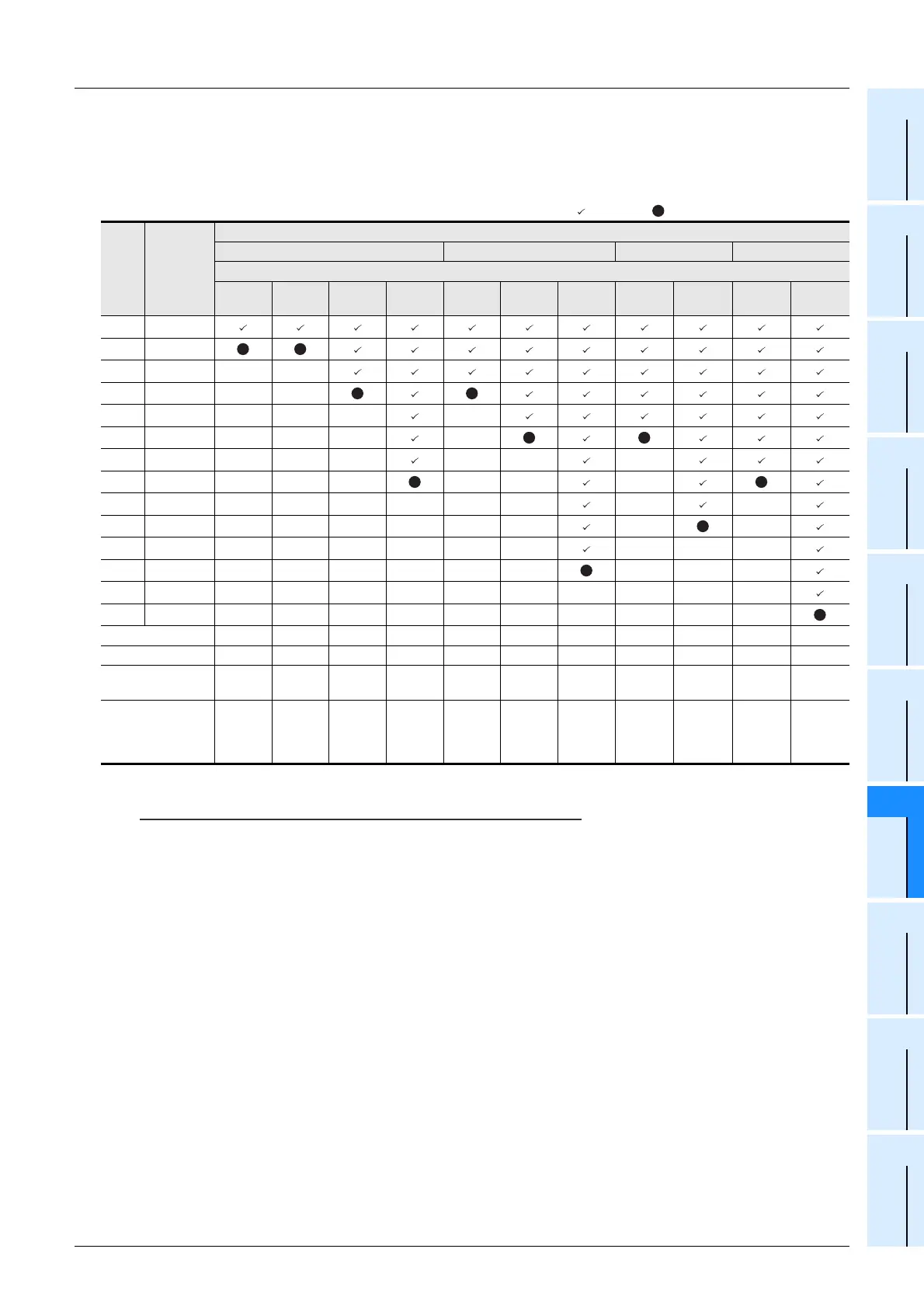
2) Details for the buffer memory allocation related to remote outputs (RY) when the expanded cyclic
transmission is set
The table below shows details for the buffer memory allocation related to remote outputs (RY)
when the expanded cyclic transmission is set.
Caution
• RY for the upper word in the last station is occupied as the system area.
• When the TO instruction (or direct buffer memory specification) is executed, writing is invalid. When the
FROM instruction (or direct buffer memory specification) is executed for reading from an area without
assigned link points, the reading operation results in "0" being read.
: User area : System area -: With no allocation
BFM
No.
Remote
input
RX number
Number of occupied stations
Occupies 1 station Occupies 2 stations Occupies 3 stations Occupies 4 stations
Expanded cyclic setting
Single Double
Quadru
ple
Octuple Single Double
Quadru
ple
Single Double Single Double
#120 RY00-0F
#121 RY10-1F
#122 RY20-2F - -
#123 RY30-3F - -
#124 RY40-4F - - - -
#125 RY50-5F - - - -
#126 RY60-6F - - - - - -
#127 RY70-7F - - - - - -
#128RY80-8F------ - -
#129RY90-9F------ - -
#130RYA0-AF------ - --
#131RYB0-BF------ - --
#132RYC0-CF-------- - -
#133RYD0-DF--------- -
User area points 16 16 48 112 48 80 176 80 144 112 208
System area points1616161616161616 1616 16
Total number of
points
32 32 64 128 64 96 192 96 160 128 224
Buffer memory
points
(System area is
included)
22484612610814

 Loading...


