I
6.
.
',)
HOW
TO
USE
EACH
FUNCTION
UECIA
[Explanation)
(1)
Not
only
the program
is
read
by
an operation that is the same as the read
by the step number, but the conductivity state, ON/O,FF state
of
a device
contact,'and the'currmt valu&f a device are also monitored.
However, the conductivity state of an AOJ2CPU, A3HCPU, A3MCPU,
A2ACPU(SI)
and
.A3ACPU
will
not
be
not displayed.
(2) Explanation
of
display contents
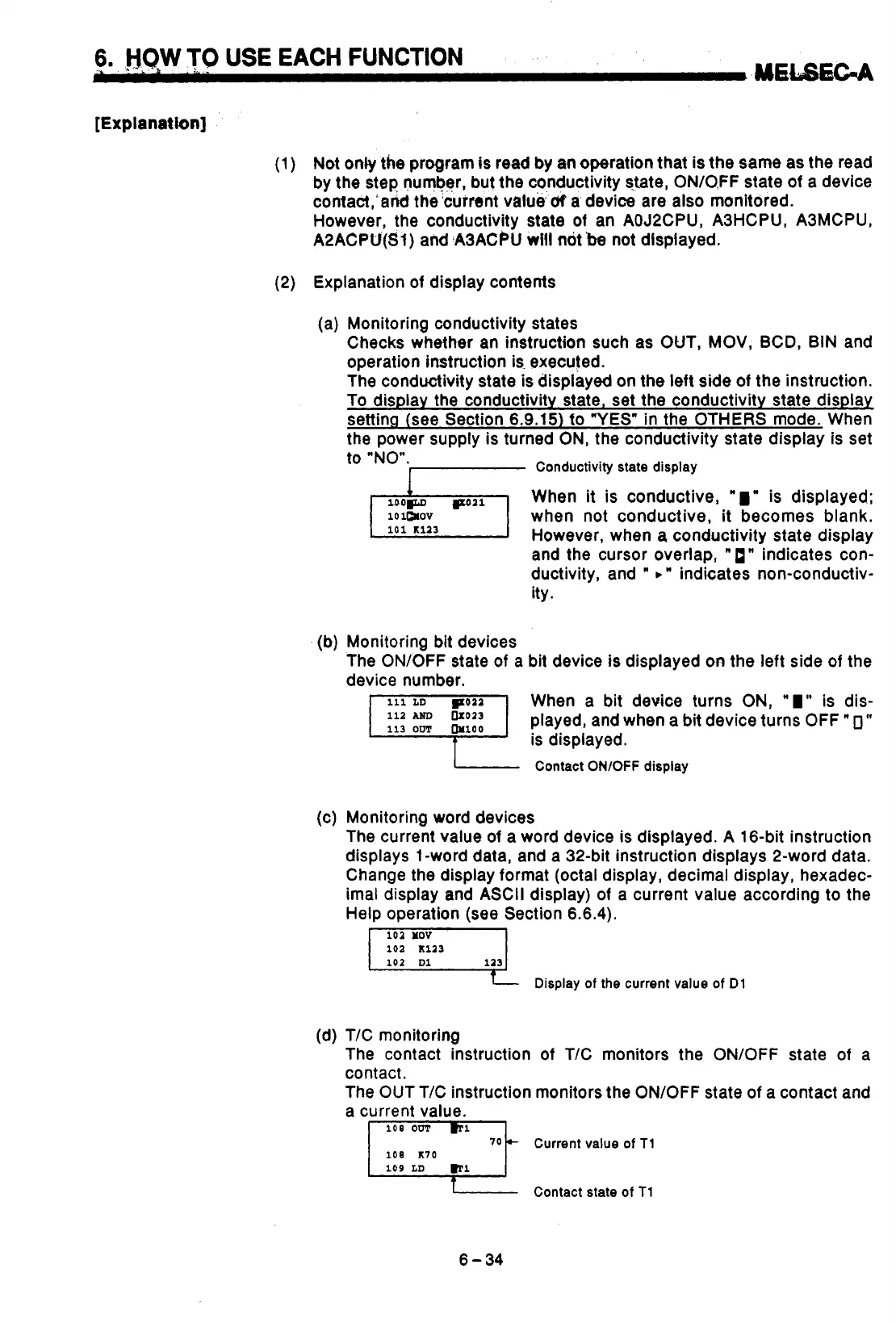
(a) Monitoring conductivity states
Checks whether an instruction such as OUT,
MOV,
BCD, BIN and
operation instruction is. executed.
The conductivity state
is
displayed on the left side of the instruction.
To display the conductivity state, set the conductivity state display
sefting (see Section
6.9.15)
fo
"YES"
in the OTHERS mode. When
the power supply is turned
ON,
the conductivity state display is set
to "NO".
Conductivity state display
When it is conductive,
'1"
is displayed;
10
1mov
when not conductive, it becomes blank.
However, when
a
conductivity state display
and the cursor overlap,
"
1"
indicates con-
ductivity, and
'
b"
indicates non-conductiv-
ity.
(b) Monitoring bit devices
The ON/OFF state
of
a bit device is displayed on the left side
of
the
device number.
When a bit device turns ON,
"
I"
is dis-
is displayed.
Contact
ONlOFF
display
played, and when a bit device turns OFF
"
0"
(c) Monitoring word devices
The current value
of
a word device is displayed.
A
16-bit instruction
displays
1
-word data, and a 32-bit instruction displays 2-word data.
Change the display format (octal display, decimal display, hexadec-
imal display and ASCII display)
of
a current value according
to
the
Help operation (see Section 6.6.4).
102
HOV
102
~1a3
102
Dl
113
Display
of
the current value
of
Dl
(d) T/C monitoring
The contact instruction
of
T/C monitors the ON/OFF state
of
a
contact.
The
OUT
T/C instruction monitors the ON/OFF state
of
a contact and
a current value.
108
K70
Current value
of
T1
Contact state
of
T1
Y
I
6-34

 Loading...


