4 - 6 4 - 6
MELSEC-Q
4 SETUP AND PROCEDURES BEFORE STARTING THE OPERATION
1) LED displays
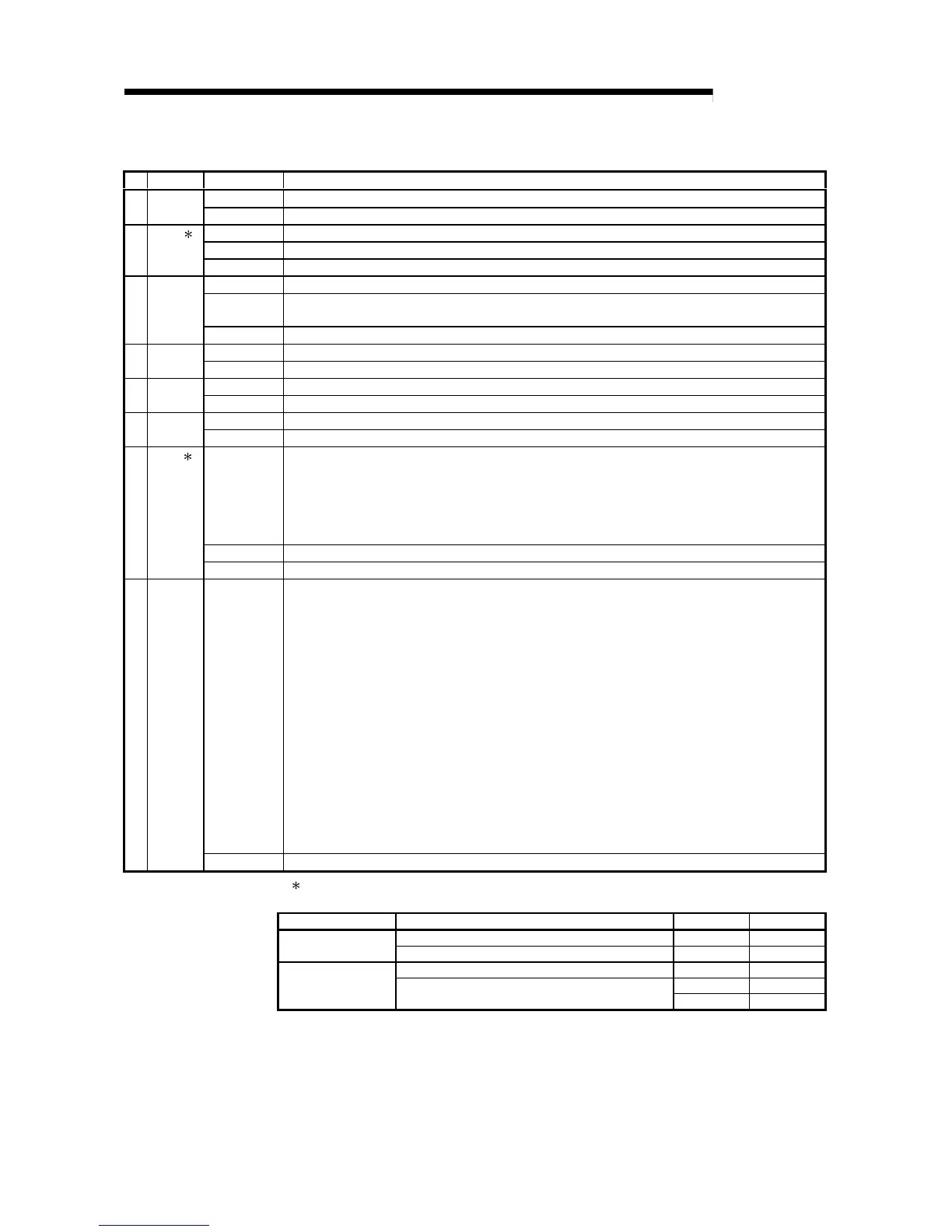
No. Name LED status Description
1 RUN Green on Module operating normally
Off WDT error occurred (hardware error)
2REM. 2 Green on Module operating normally.
Green flashing Parameters being written to flash ROM or device is in test mode.
Off In remote initialization, error (WDT error, blown fuse error, input/output verification error, etc.)
3 T.PASS Green on Executing baton pass (being joined in a network)
Green flash Test is determined to have completed normally when this LED flashes 20 times (approximately 10 s)
during the test.
Off Baton pass not yet executed (the host is disconnected from the network)
4 D.LINK Green on Data link being executed (cyclic transmission is being executed)
Off Data link not yet executed (parameter receiving not completed, host CPU error, data link stop instructed, etc.)
5 SD Green on Data being sent
Off Data not yet sent
6 RD Green on Data being received
Off Data not yet received
7 ERR.
2 Red on • Station setting error (other than 1 to 64), mode setting error (prohibited setting), operating condition
setting error due to parameters.
• A station with the same number already exists in the network.
• Host is designated as remote master station in spite of a remote master station already existing in the
network.
• Abnormality in parameters received from the remote master station.
Flashing An error was detected while testing the network module.
Off Normal status
8 L ERR. Red on A communication error occurred (one of the following communication errors has occurred):
CRC : Error generated by an abnormal cable, noise, etc.
OVER : This error occurs when the next data is received before the last receive data is loaded into the
module, and the data is overwritten. It is caused by a hardware error in the receive area of the
network module.
AB.IF : This error occurs when more than the specified number of bits are set to "1" among the receive
data in the frame, or when the receive data is shorter than the specified data length.
TIME : This error occurs when a baton pass was not handed to the host within the monitoring time.
DATA : This error is caused when abnormal code data is received.
UNDER : This error occurs when the internal processing of the send data was not executed at a fixed
interval.
LOOP : This error occurs when the forward or reverse loop line is faulty and the power to the adjacent
station, which sends data to the host station, is turned OFF or the cable connector is faulty.
<Corrective action>
Check the cables and connectors (detached or loosened connectors, wrong IN/OUT connections,
broken or damaged cables, improper cable routing, etc.)
For more details, see the "Network Diagnostics" (Section 8.1).
Off No communication error
2: When a remote I/O module is used in a redundant power supply system, the REM. LED and ERR.
LED indicate errors as follows according to the failure causes of the power supply module.
Power supply module Failure cause REM. LED ERR. LED
Input power supply off, fuse blown Off OnFailure of only one
module
Internal failure On On
Input power supply off, fuse blown Off Off
Off On
Failure of both the two
modules
Internal failure (Both the LEDs are off or on depending
on the failure part.)
On On
The faulty power supply module can be confirmed by the error code. (Refer to section 8.3.2.)
When a remote I/O module of function version C or later is used, the ERR. LED remains off even if
one or two power supply modules fail.
Confirm the failure of the power supply module on the LED of the module. If the power supply module
is mounted on an extension base unit, the error can also be confirmed by the ERR contact of the
power supply module. (For the specification of the LED of the power supply module, refer to QCPU
User's Manual (Hardware Design, Maintenance and Inspection).)

 Loading...


