4 - 14 4 - 14
MELSEC-Q
4 SETUP AND PROCEDURES BEFORE STARTING THE OPERATION
4.8 Cable Connections
4.8.1 Optical loop system
(1) Precautions when connecting
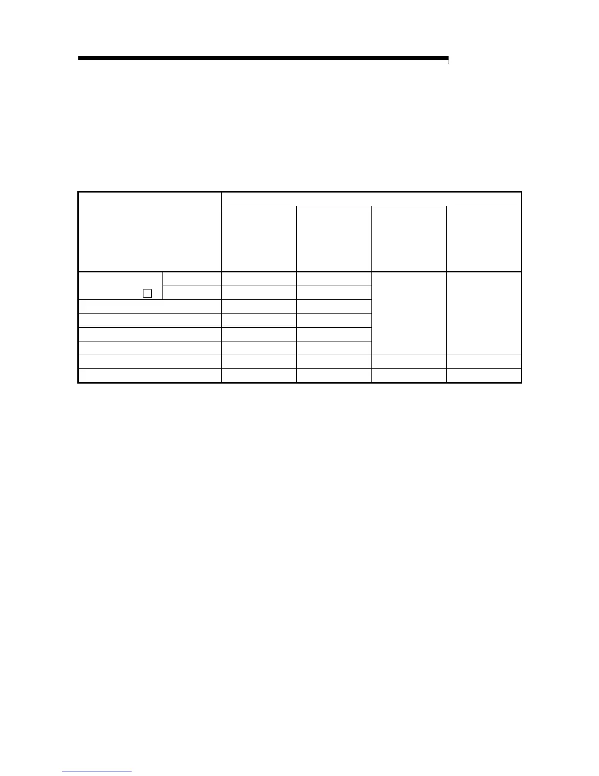
(a) The type of cables that can be used will vary according to the distance
between stations.
Interstation distance (m)
Type
QJ71LP21,
QJ71LP21-25,
QJ71LP21S-25,
QJ72LP25-25 :
10 Mbps
QJ71LP21-25,
QJ71LP21S-25,
QJ72LP25-25 :
25 Mbps
QJ71LP21G
QJ72LP25G
QJ71LP21GE
QJ72LP25GE
L type 500 200
SI fiber-optic cable
(Old type: A-2P-
)
H type 300 100
SI fiber-optic cable 500 200
H-PCF fiber-optic cable 1000 400
Broad-band H-PCF fiber-optic cable 1000 1000
QSI fiber-optic cable 1000 1000
Must not be used Must not be used
GI-50/125 fiber-optic cable Must not be used Must not be used 2000 Must not be used
GI-62.5/125 fiber-optic cable Must not be used Must not be used Must not be used 2000
(b) When optical fiber cable is connected, there are restrictions for the bending
radius of the cable.
Check the cable used for specific details.
(c) Maintain the bending radius of the optical fiber cable within the allowable
range using a tool for securing the optical fiber cable bending radius.
This tool may be purchased from Mitsubishi Electric System Service, Inc, or
your nearest dealer. Please inquire for more information.
(d) When laying the optical-fiber cables, do not touch the fiber cores of the cable
and module connectors, and do not let dust or particles collect on them.
If oil from hands, dust or particles adhere to the cores, the accumulated
transmission loss may cause malfunctions in the data link.
(e) When attaching or detaching the optical fiber cable to/from the module, pull
or insert the cable by holding the cable connector securely with your hand.
(f) Connect the cable and module connectors securely until you hear a "click"
sound.
 Loading...


