-
16
-
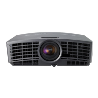
12. Removal of LCD BLOCK
Note: Wear a wrist band, etc. to prevent static electricity
when replacing the LCD Block. The LCD may be
damaged by static electricity.
1. Remove the Top Case Assy and the Terminal Board
following “1.Removal of TOP CASE ASSY and
SPEAKER”. (Fig. 3-1)
2. Remove the Terminal Assy (MAIN PCB ASSY, INLET
PCB ASSY, and TERMINAL PCB ASSY) following
“4.Removal of TERMINAL ASSY (MAIN PCB ASSY,
INLET PCB ASSY, and TERMINAL PCB ASSY) ”.
(Fig. 3-4)
3. Remove the Optical Unit following “8. Removal of
OPTICAL UNIT”. (Fig. 3-8)
4. Remove the Lens Unit following “11. Removal of LENS
UNIT”. (Fig. 3-11)
5. Remove the two (a) screws and the Cooling Fan Unit
Assy (Intake) , Fan Holder and Duct2 (lid) as shown in
Fig. 3-12.
6. Remove the (b) screw and take out the LCD Block as
shown in Fig. 3-12.
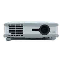
11. Removal of LENS UNIT
1. Remove the Top Case Assy and the Terminal Board
following “1.Removal of TOP CASE ASSY and
SPEAKER”. (Fig. 3-1)
2. Remove the Terminal Assy (MAIN PCB ASSY, INLET
PCB ASSY, and TERMINAL PCB ASSY) following
“4.Removal of TERMINAL ASSY (MAIN PCB ASSY,
INLET PCB ASSY, and TERMINAL PCB ASSY) ”.
(Fig. 3-4)
3. Remove the Optical Unit following “8. Removal of
OPTICAL UNIT”. (Fig. 3-8)
4. Remove the four (a) screws and the Lens Unit from the
Optical Unit as shown in Fig. 3-11.
 Loading...