Chapter Six: Remote Digital Logic Control How To Select the Digital Input Functions
113
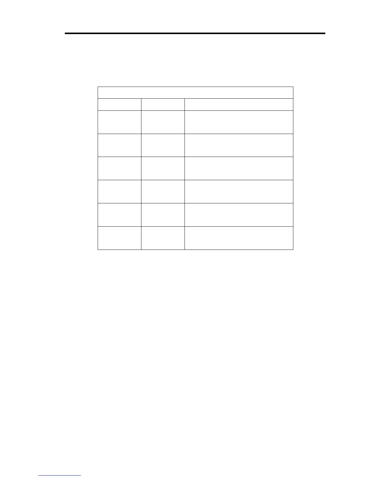
Digital Input Functions (Continued)
I/O Pin No. State Digital Input Function
15 Low
High
Selects set point B
No function
16 Low
High
Selects set point A
No function
24 Low
High
No function
No function
25 Low
High
Performs the remote zero function
No function
26 Low
High
Stop the valve
No function
27 Low
High
Open the valve
No function
Table 17: Digital Input Functions
How To Set the Analog Set Point Inputs
The analog set point inputs, (+) set point and (-) set point (pins 33 and 34 respectively on the
Interface connector), are fully differential. The (-) set point must be connected to a ground to
work correctly, and it is recommended that it be connected to ground at the source of the set
point signal. If suitable ground is not available at source of set point, connect pin 34 to pin 35.,
Refer to Table 8, for the complete Interface connector pinout.
 Loading...