Chapter Four: Local Operation Operation
59
Operation
How To Activate a Set Point
Activating a set point commands the 651 unit to control to that set point. Only one set point can
be active at a time.
How To Activate an Internal Set Point
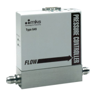
The internal set points (A to E) are activated by pressing the appropriate key on the front panel
of the 651 controller (refer to Figure 8.).
To activate an internal set point:
1. Press the appropriate set point key (A to E) on the front panel.
The LED in the upper left corner of the activated set point key illuminates and the
display changes to reflect the activated set point. Once the key is pressed, the Pressure
and Position display screen appears and displays either the set point pressure or valve
position, and the actual pressure. The LED remains lit until another set point (or valve
function) is chosen.
How To Activate the Analog Set Point
The analog set point is activated through the Interface connector on the rear panel of the 651
controller (refer to Figure 9).
Note
When the 651 unit is configured for PID control, two gain parameters are
maintained for each pressure set point. When an analog set point is used
with PID control, the gain parameters associated with any of the pressure
set points (A to E) may be used. The unit uses the gain values for set
point A by default.
To specify which set point’s gain parameters to use:
1. Apply a TTL low level signal to the I/O connector pin assigned to the desired set point.
Refer to Table 8, for the I/O connector pinout.
The TTL low level signal (0 to 0.8 Volts) is “level sensitive” meaning that once the signal
is held low, the 651 unit may take up to 50 milliseconds to recognize the command. The
line must be held low continuously for the 651 unit to use the selected parameters. Once
the signal goes high, the controller will default back to set point A parameters within 50
milliseconds.
For example, to apply the gain parameters associated with set point C to the analog set point,
apply a 0 to 0.8 Volt signal to pin 14 on the I/O connector for as long as you wish to use those
parameters. There is no LED on the front panel to indicate that the system is under analog set
point control (in fact, all LEDs on the front panel go out).
 Loading...