Electrical Connections Cha
ter Three: Overview
32
9-Pin Type “D” Connector
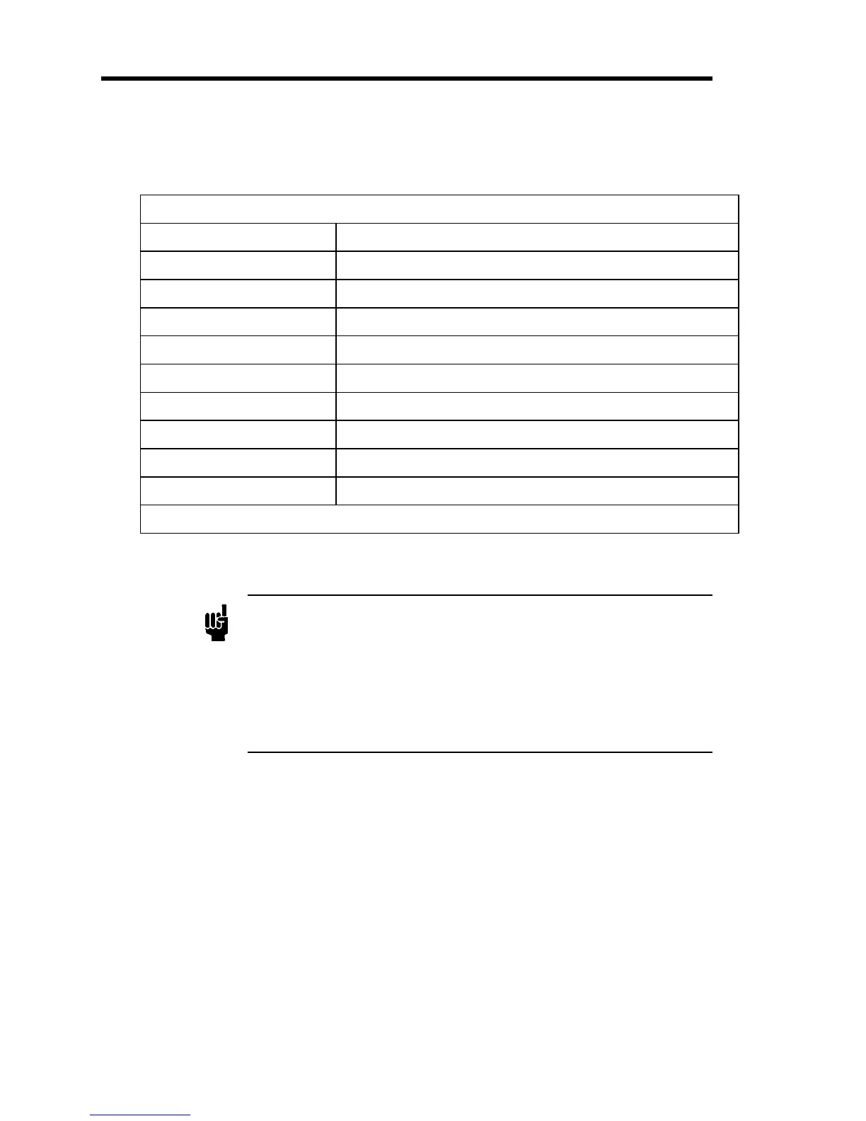
Table 8 lists the pinout of the 9-pin Type “D” connector for a mass flow controller.
9-Pin Type “D” Connector Pinout
Pin Number Assignment
1 Valve Open/Close*
2 Flow Signal Output
3 +15 V
4 Power Common
5 -15 V
6 Set Point*
7 Signal Common
8 Signal Common
9 MKS Test Point*
* For an MFC only, No Connection for an MFM
Table 6: 9-Pin Type “D” Connector Pinout
Note
1.
Chassis ground is not available on a separate pin. Instead, it is
carried out throu
h the cable shieldin
. Be sure that the connector on
the other end of the cable is properly grounded to its chassis ground.
2.
The 0 to 5 VDC flow signal output comes from pin 2 and is
referenced to pin 7 (signal common).
3.
Use any appropriate 0 to 5 VDC input signal of less than 20K ohm
source impedance referenced to pin 7 as the set point signal to pin 8.
 Loading...