How To Adjust the Valve Preload (MFC only) Cha
ter Seven: Troubleshootin
52
5. Set the gas supply regulator to the maximum expected operating pressure of your
processing system.
Warning
Follow your corporate policy on handling toxic or hazardous
gases. Your corporate policy on handling these gases
supersedes
the instructions in this manual. MKS assumes no
liability for the safe handling of such materials.
If appropriate, remove the MFC from the process tool and
make the adjustments using a surrogate gas.
6. Close all isolation valves in the system, both upstream and downstream of the MFC.
7. Zero the unit, following the instructions in
How To Zero the Flow Controller,
page 40.
8. Disconnect one electrical valve lead from its post on the PC Control board and connect a
DMM in series. Set the DMM to measure current in the 10 to 100 mA range.
9. Open all upstream and downstream isolation valves in the system.
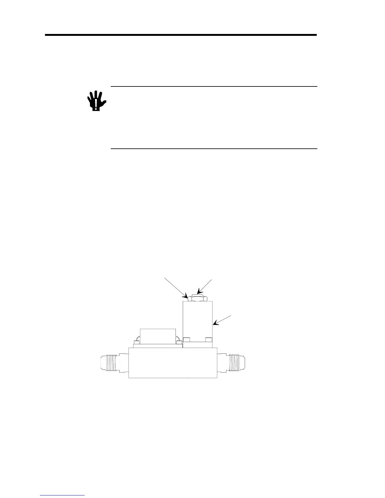
10. Hold the centershaft in place with a
3
/
16
” allen wrench and loosen the jam nut using a
9
/
16
”
crescent wrench.
Refer to Figure 9 for the location of the lock nut and centershaft.
Jam Nut
Centershaft
Valve Coil
Enclosure
Figure 9: Location of the Lock Nut and Centershaft
11. Provide a set point input signal to the MFC of 0.25 Volts to represent 5% flow.
 Loading...