How To Adjust the Valve Preload (MFC only) Cha
ter Seven: Troubleshootin
54
18. Observe the MFC output and control valve current.
Record the valve current.
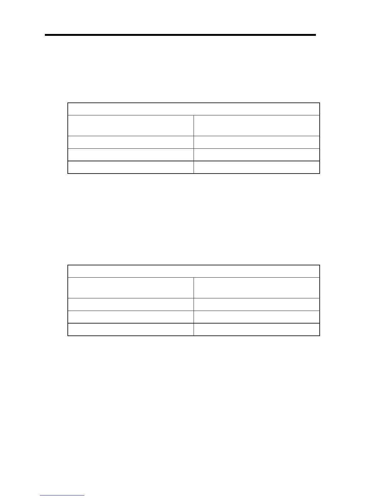
The MFC output should be 5.0 Volts (100%) and the valve current no greater than the
limits in Table 10. If the valve current exceeds these limits, return the unit to MKS for
service.
Maximum Valve Currents
UUT Flow Capacity
(N
2
Equivalent)
Maximum Valve Current at
100% Set Point and Minimum Pressure
50 sccm and under 39 milliAmps
100 to 500 sccm 45 milliAmps
1000 sccm and above 51 milliAmps
Table 10: Maximum Valve Currents
19. Re-adjust the Valve Current Limit Potentiometer, R85.
a. Find the current limiting potentiometer, R85, on the PC board.
Refer to Figure 10, page 55. R85 is located in the top right hand corner of the board.
It is the only
black
potentiometer on the board and is much smaller than the others.
b. Determine the required valve current limit by adding the appropriate headroom from
Table 11 to the valve current recorded in Step 18.
Valve Current Headroom
UUT Flow Capacity
(N
2
Equivalent)
Required Valve Current
Headroom
50 sccm and under 24 milliAmps
100 to 500 sccm 18 milliAmps
1000 sccm and above 12 milliAmps
Table 11: Valve Current Headroom
c. Provide a 5 V set point signal and turn the gas supply off.
d. When the indicated flow output has dropped to zero, adjust R85 until the required
valve current limit is obtained. Note that
counterclockwise
rotation
increases
the
maximum current, while
clockwise
rotation
decreases
it.
20. Remove the DMM and reconnect the valve lead.
21. Reposition the enclosure over the unit and tighten the retaining screws.
22. Reconnect the cable.
 Loading...